Introduction
In the world of electrical circuits, capacitors are important for understanding and enhancing alternating current (AC) systems. They serve not only to store and release electrical charge but also to influence the impedance of AC circuits. This article discusses the significance of capacitor impedance in analyzing AC circuits and provides guidance on how to calculate it. We'll explore capacitor impedance in AC circuits, examining capacitance details, the roles of capacitors in AC circuits, and their significance in low and high pass filters. Understanding the impedance of capacitors becomes important when analyzing AC circuits because it combines both resistance and reactance, offering a detailed perspective on the circuit's behavior. This exploration will guide you through the basics of capacitance, the functions of capacitors in AC circuits, and reveal how impedance affects the performance of these circuits.
Now, let's talk about capacitors and how they function in different filters like low pass and high pass filters. We'll also explore how their impedance changes with frequency. Additionally, we'll learn how to calculate capacitor impedance, enabling you to analyze and design AC circuits more effectively. So, let's explore capacitors together, understanding their functions, how impedance operates in AC circuits, and how to utilize capacitor impedance for improved circuit performance.
What Is Capacitance?
Capacitance is a fundamental concept in the field of electronics and electrical engineering. It refers to the ability of a component or system to store electrical energy in the form of an electric field. Capacitance is the measure of how much electrical charge can be stored in a capacitor for a given voltage. A capacitor is a passive electronic component that consists of two conductive plates separated by an insulating material known as a dielectric. When a voltage is applied across the plates, an electric field is created, and the capacitor stores energy in this field.
The capacitance of a capacitor is determined by several factors, including the surface area of the plates, the distance between them, and the properties of the dielectric material. Capacitance is measured in farads (F), with smaller units such as microfarads (μF) and picofarads (pF) commonly used in practical applications. Capacitors are widely used in electronic circuits for various purposes. They can store energy to provide a temporary power source, filter out unwanted frequencies, and stabilize voltage levels. Capacitance also plays an important role in timing circuits, oscillators, and many other electronic devices.
What are Capacitors?
A capacitor is an electronic component that stores and releases electrical energy. It is commonly used in various electrical and electronic circuits to perform a wide range of functions. We have already discussed Capacitors' Symbols. Capacitors consist of two conductive plates separated by a dielectric material. Conductive plates, often metal, are separated by an insulating dielectric. Applying voltage charges the capacitor, storing energy. This stored energy can then be released when needed. Understanding how to discharge a capacitor safely is important, especially when working with electronic components to avoid any potential dangers.
The Function of a Capacitor in an AC Circuit
In an alternating current (AC) circuit, capacitors manage the flow of electrical energy. A capacitor is an electronic component that stores and releases electrical charge. It consists of two conductive plates separated by an insulating material called a dielectric. The primary function of a capacitor in an AC circuit is to store and release electrical energy. When connected to an AC power source, the capacitor charges and discharges in sync with the alternating current. Throughout the positive half-cycle of the AC waveform, the capacitor charges up, storing electrical energy. Subsequently, during the negative half-cycle, the capacitor discharges, releasing the stored energy back into the circuit. Capacitors are commonly used in AC circuits for various purposes. In AC circuits, the power factor represents the efficiency of power transfer. A low power factor can result in wasted energy and increased utility costs. Capacitors can be strategically placed in the circuit to improve the power factor by compensating for the reactive power and reducing the overall power consumption.
Another function of capacitors in AC circuits is to filter out unwanted noise or voltage fluctuations. By selectively allowing certain frequencies to pass through while blocking others, capacitors can smooth out the waveform and provide a more stable output voltage. Additionally, capacitors are used in timing circuits, voltage regulation, and energy storage systems. Their ability to store and release electrical charge makes them adaptable components in AC circuits. Capacitors in AC circuits serve the important function of storing and releasing electrical energy. They help in power factor correction, noise filtering, timing circuits, voltage regulation, and energy storage.
Components Free Worldwide Shipping
Capacitors in Low Pass Filters
In a low pass filter, the capacitor is strategically placed to allow low-frequency signals to pass through while blocking high-frequency noise or interference. The value of the capacitor determines the cutoff frequency of the low pass filter. A larger capacitor value will result in a lower cutoff frequency, allowing lower-frequency signals to pass through. Conversely, a smaller capacitor value will increase the cutoff frequency, attenuating more of the low-frequency signals. However, they may introduce some parasitic effects, such as inductance and resistance, which can affect the filter's performance at higher frequencies. In some cases, multiple capacitors may be used in parallel or in series to achieve the desired capacitance value. This allows for more flexibility in designing low pass filters with specific cutoff frequencies.
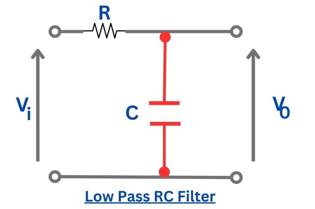
Low Pass RC Filter
The provided diagram illustrates a low-pass RC filter where the capacitor is connected in parallel to the ground. In this configuration, high-frequency signals are directed towards the ground, effectively blocking any high-frequency noise beyond the cut-off frequency from reaching the load.
The cutoff frequency of a low-pass RC filter is determined by the given equation.
fc = 1 / 2 π T
fc = 1 / 2 π RC
A deeper insight into the filter's characteristics can be gained by examining its behavior through the Laplace transform of the corresponding transfer function, as expressed below.
H(s) = Vo / Vi = (1/sC)/(1/sC + R)
= 1/(sRC + 1)
Capacitors in High Pass Filters
When a high-frequency signal is applied to a high pass filter, the capacitor charges and allows the signal to pass through, while blocking low-frequency signals. The value of the capacitor determines the cutoff frequency of the high pass filter. A larger capacitor value will result in a lower cutoff frequency, allowing a broader range of lower frequencies to pass through. Conversely, a smaller capacitor value will increase the cutoff frequency, allowing only higher frequencies to pass. Consider factors such as capacitance value, voltage rating, and tolerance. Additionally, the type of capacitor, such as ceramic, electrolytic, or film, can impact the performance of the high pass filter.
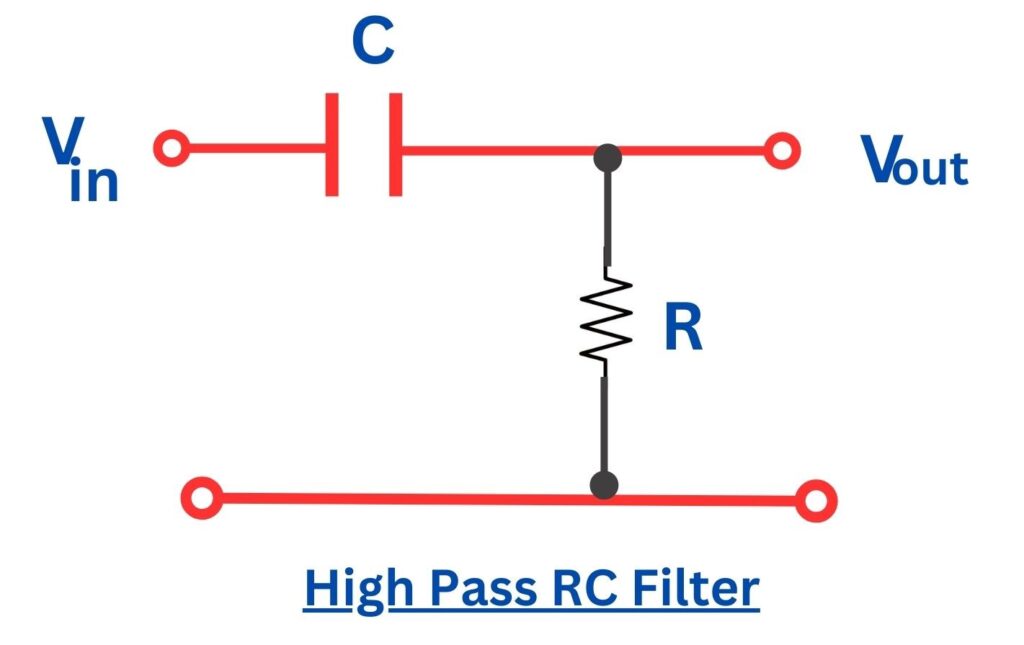
High Pass RC Filter
The cut-off frequency for the RC high-pass filter is determined by the following expression:
fc = 1/ 2 π T = (1 / 2 π R C)
The equation provided describes the transfer function of the high-pass RC filter
H(s) = Vo / Vi = (1/sC) / (1/sC + R)
= 1 / (sRC + 1)
Understanding Impedance in an AC Circuit
Impedance is similar to resistance in a direct current (DC) circuit, but it takes into account both resistance and reactance. Reactance is a measure of the opposition to the flow of AC caused by capacitance or inductance in the circuit. Impedance is a comprehensive measure that encompasses both resistance and reactance in an electrical circuit. Essentially, it represents anything that hinders the flow of electrons within the circuit, influencing the generation of current. Found in all components of the circuit and across various electrical circuits, impedance is denoted mathematically as the letter Z and is measured in ohms. It serves as a unified concept, combining both resistance and reactance. In phasor terms, impedance (Z) is expressed as the sum of resistance (R) and reactance (X), where reactance is further broken down into inductive (XL) and capacitive (XC) components.
The phasor equation is given by
Z = R + jX,
where X = XL + XC.
This representation captures the interplay of resistance and reactance in the impedance of an electrical circuit.
How to Calculate a Capacitor's Impedance
To calculate the impedance of a capacitor in an AC circuit, we need to consider its reactance. Reactance is inversely proportional to the frequency of the AC signal and the capacitance of the capacitor. The formula to calculate the reactance of a capacitor is Xc = 1 / (2πfC), where Xc is the reactance, f is the frequency, and C is the capacitance.
Once we have the reactance, we can calculate the impedance using the formula Z = Xc. The impedance of the capacitor is important in determining the behavior of the circuit and can be used to analyze voltage and current relationships.
Let's say we have a capacitor with a capacitance of 10 microfarads (µF) and we want to calculate its impedance at a frequency of 1 kilohertz (kHz).
Using the formula mentioned above:
Z = 1 / (2πfC)
Substituting the given values:
Z = 1 / (2π * 1000 * 10-6)
Z ≈ 1 / (6.283 * 0.001 * 10-6)
Z ≈ 159.15 ohms
Therefore, the impedance of the capacitor at a frequency of 1 kHz is approximately 159.15 ohms.
Conclusion
In conclusion, capacitor impedance plays an important role in AC circuit analysis. Understanding the concept of impedance and how to calculate it allows us to design and analyze AC circuits more effectively. Capacitors are versatile components that find applications in various circuit designs, such as low pass filters and high pass filters. By considering the impedance of capacitors, we can optimize circuit performance and achieve the desired electrical characteristics. Additionally, understanding impedance control in PCBs further enhances our ability to adapt circuits for specific applications.
Capacitors and their impedance play an important role in AC circuit analysis. By understanding the concept of impedance and how to calculate it for capacitors, you can effectively design and analyze AC circuits. Capacitors are versatile components that can be used for energy storage, filtering, and coupling applications. Whether you are an electrical engineer, a hobbyist, or a student, having a solid understanding of capacitor impedance will enhance your ability to work with AC circuits. We hope this article has provided you with valuable insights into the importance of capacitor impedance, how to calculate it, and the role of impedance control in Capacitors.
Comment