ESP32 WiFi + Bluetooth Module is a prototyping board developed by Espressif Systems It is based on the ESP32, a microprocessor developed to be not only used in large intermediate and complex level projects but also in wearable electronics and IoT projects. On the ESP32 development board, you get WiFi and Bluetooth along with an inbuilt antenna and supports ultra-low power consumption.
It can be used in high-end user products such as; for controlling and monitoring sensors from anywhere in the world through GPRS/4G-LTE/WiFi. It can also be used in Low-Power sensor networks, it can be used for voice encoding, MP3, decoding, and Music Streaming. And that’s not all, since the ESP32 is also based on the Low Energy Bluetooth technology, so using the ESP32 on-board Bluetooth, efficient Home and Office automation systems can be developed with dedicated cell phone applications. The ESP32 chip is designed to be scalable and adaptive. What makes the ESP32 so special are the two cores that can be individually controlled and thus multiple tasks can be run at the same time. You can use one core for monitoring the sensors and use another core for sending that data to an IoT cloud platform. ESP32’s clock frequency is adjustable from 80MHz to 240MHz.
ESP32 WiFi + Bluetooth module has multiple IO pins, ranging from capacitive touch sensors, low-noise sensor amplifiers, Hall sensors, SD Card interface, Ethernet, I2C, UART, and high-speed SDIO/SPI. I have been personally using ESP32 for years and I believe it's perfect for wearable electronics or battery-powered applications as the ESP32 chip uses less than 5 µA. Moreover, ESP32 can support data rates of up to 150Mbps and 22 dBm output power at the PA in order to allow for the widest physical range.
ESP32 Specifications and Pinout:
- -Current – Receiving: 80 mA.
- -Voltage – Supply: 2.2 V ~ 3.6 V.
- -Current – Transmitting: 80 mA.
- -Number of pins supported: 30
- -Data Rate: 54 Mbps.
- -Frequency: 2.4 GHz.
- -Mounting Type: Surface Mount.
- -Operating Temperature: -40°C ~ 85°C.
- -Power – Output: 16.5dBm.
- -Protocol: 802.11b/g/n/d/e/i.
- -RF Family/Standard: WiFi.
- -Sensitivity: -98dBm.
- -Serial Interfaces: I²C, I²S, SPI, UART.
- -Integrated 520 KB SRAM.
- -Hybrid Wi-FI& Bluetooth.
- -High level of integration.
- -Ultra-low-power management.
- -4 MB Flash.
- -On-board PCB antenna.
The ESP32 peripherals include:
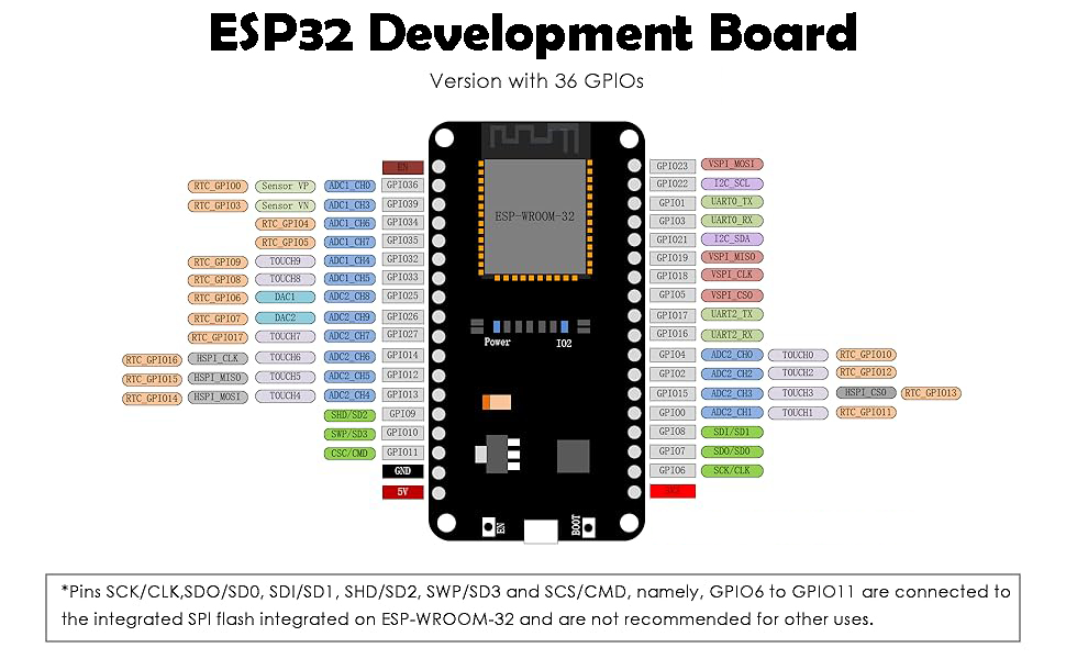
- -18 Analog-to-Digital Converter (ADC) channels
- -2 Digital-to-Analog Converters (DAC)
- -10 Capacitive sensing GPIOs
- -2 I2C interfaces
- -3 SPI interfaces
- -3 UART interfaces
- -16 PWM output channels
- -2 I2S interfaces
Arduino IDE:
Throughout this course, we will use the Arduino IDE “integrated development environment” for programming the ESP32 WiFi + Bluetooth Module. For the basics, you can read my article on the Arduino full course. Anyway, first you need to go to the Arduino.cc official website and download the Arduino software. On my side, I have already downloaded and installed the Arduino 1.8.19 version.
Installing ESP32 Board in Arduino IDE:
ESP32 and its other variants are not pre-installed in the Arduino IDE, so for this, first you will need to install the ESP32 board in the Arduino IDE, it hardly takes 3 to 5 minutes depending on the speed of your internet connection.
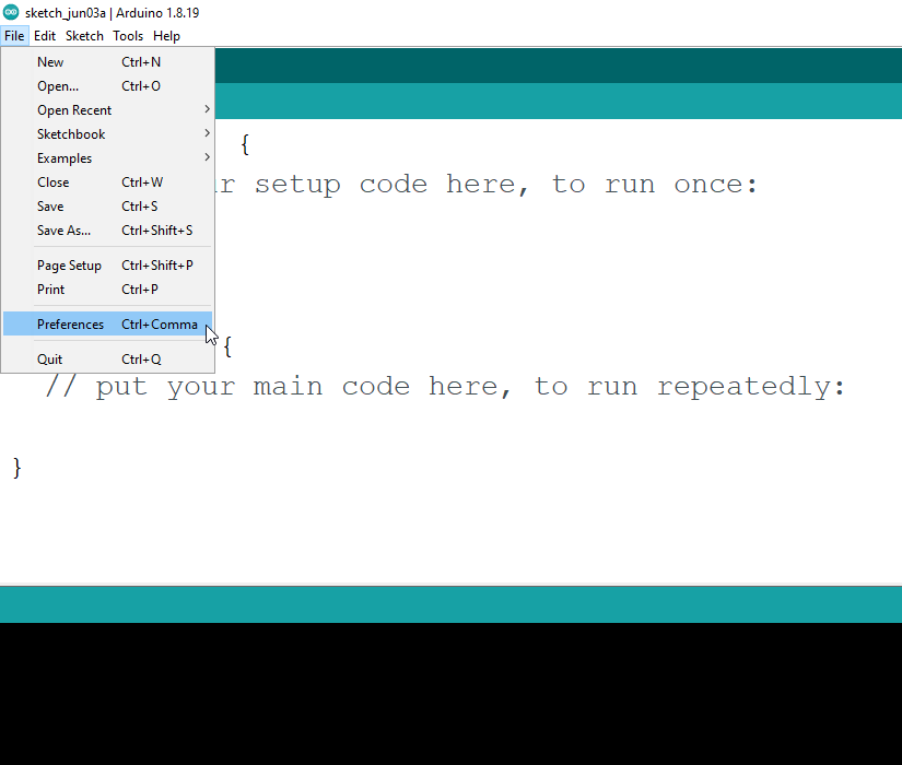
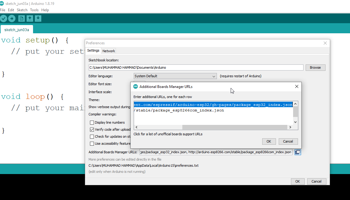
While your Arduino IDE is open, go to the File Menu and then to Preferences.
Then in the Additional Boards Manager URLs: paste the following link:
https://raw.githubusercontent.com/espressif/arduino-esp32/gh-pages/package_esp32_index.json
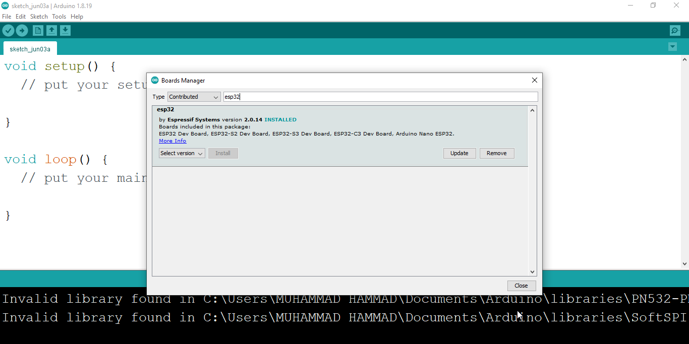
Next, go to the Tools Menu > Board > Boards Manager
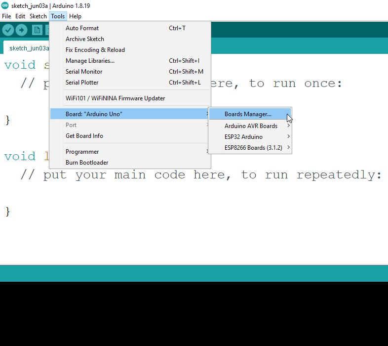
Then select contributed
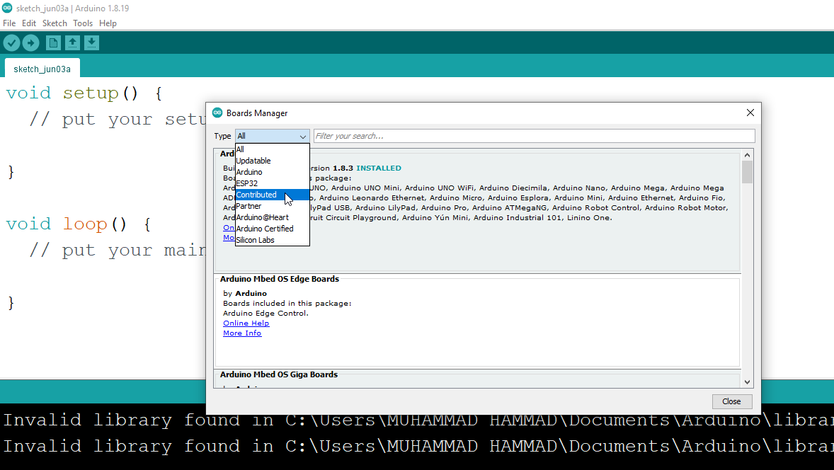
Search for ESP32, you can see that I have already installed the ESP32 board.
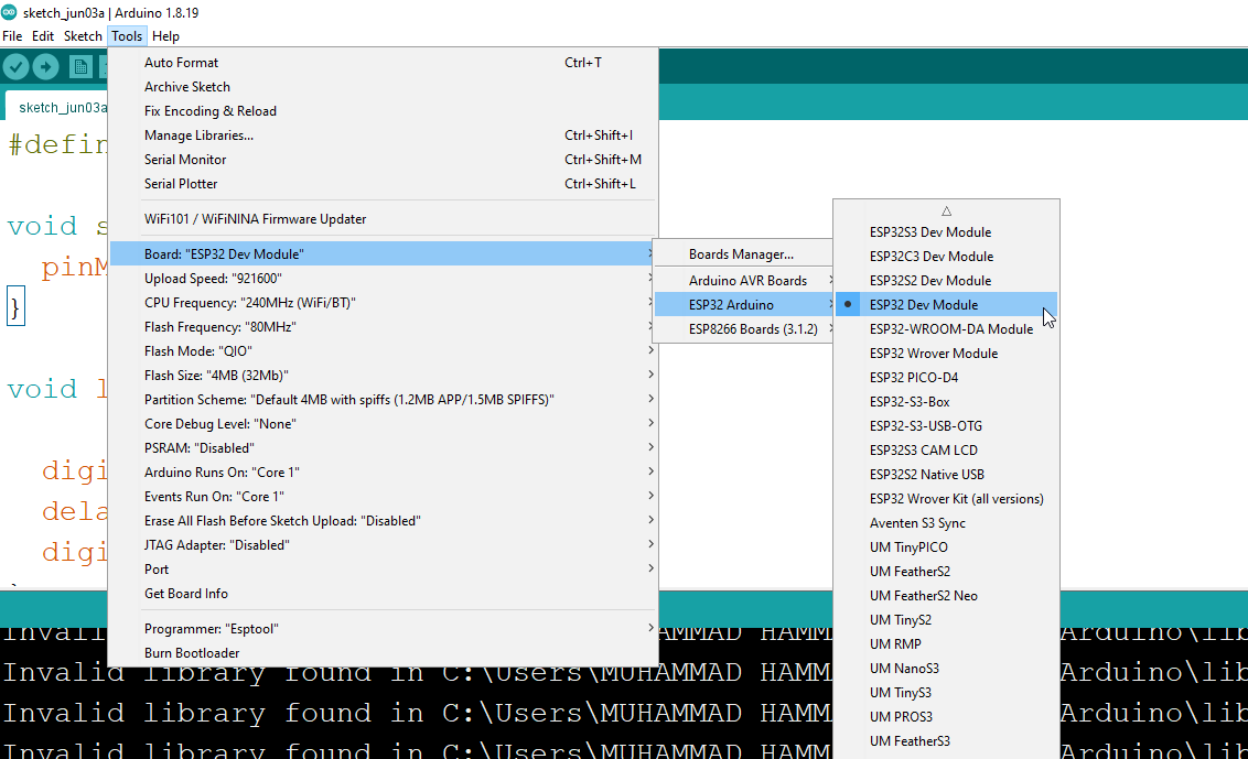
Now, our Arduino IDE is ready, so let’s go ahead and Blink the ESP32’s onboard LED connected to the GPIO 5. On some other variants of the ESP32, the onboard LED is connected to the GPIO 2, or it may be another GPIO pin; so, you will need to confirm this.
1. Blinking Built-in LED on ESP32
Select the ESP32 Dev module, then select the COM port, and finally, upload the code to the ESP32.
ESP32 Led Blinking Code:
#define ledpin 5
void setup() {
pinMode(ledpin, OUTPUT);
}
void loop() {
digitalWrite(ledpin, HIGH);
delay(1000);
digitalWrite(ledpin, LOW);
delay(1000);
}
2. External led with ESP32:
Now, let’s control an external LED. The purpose of this program is to explain, how to control any GPIO pin on the ESP32.

- -Connect the anode of the LED through a 330-ohm resistor with GPIO pin 4 of the ESP32
- -Connect the cathode of the LED with the ground of the ESP32
External LED Blinking Code:
#define ledpin 4
void setup() {
pinMode(ledpin,OUTPUT);
}
void loop() {
digitalWrite(ledpin,HIGH);
delay(1000);
digitalWrite(ledpin,LOW);
delay(1000);
}
If you compare the above programs, you will find that both the programs are exactly the same; except the pin numbers. Now, you can connect your external LED to another GPIO Pin, then change the GPIO pin to the code, and you will be able to control the same LED. Keep changing the GPIO pins, to completely understand how to control any GPIO pin on the ESP32.
After understanding, how to send a digital signal to any GPIO Pin, and how to turn the Pin ON/OFF. Next, we are going to learn how to read an Analog Sensor.
3. Push Button with ESP32:
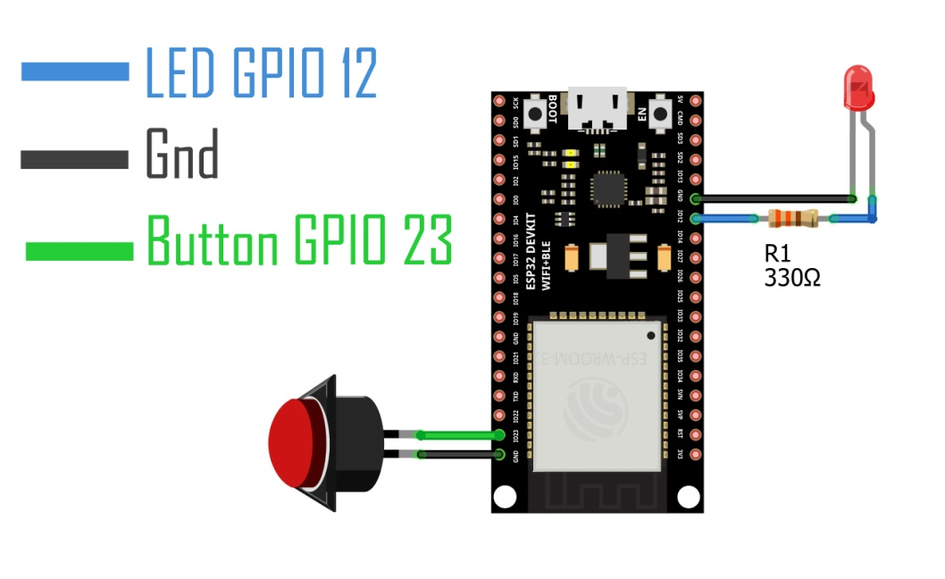
- -Connect one pin of the button with the GPIO 23 pin of the ESP32
- -Connect the other pin of the button with the Ground pin of the ESP32
- -Connect the anode of the LED through a 330 ohm resistor with GPIO pin 12 of the ESP32
- -Connect the cathode of the LED with the ground pin of the ESP32
Code:
int led =12;
int button= 23;
void setup() {
//Serial.begin(9600);
pinMode (led, OUTPUT);
pinMode (button, INPUT_PULLUP);
}
void loop() {
if(digitalRead(button) == HIGH)
{
digitalWrite(led, HIGH);
}
if(digitalRead(button) == LOW)
{
digitalWrite(led, LOW);
}
}
4. Display potentiometer value on Serial Monitor:
For this example, I have selected a Potentiometer which is basically a variable resistor. By rotating the Knob of a potentiometer we can generate different voltages. Guess what, we can read these changes in the voltage using an analog pin on the ESP32, and this is what we are going to do.
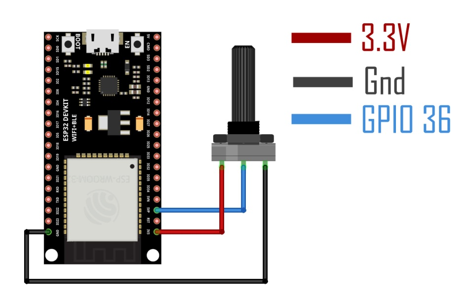
- -Connect one pin of the potentiometer with 3.3V of the ESP32
- -Connect the middle pin of the potentiometer with GPIO pin 36 of the ESP32
- -Connect the other pin of the potentiometer with the ground of the ESP32
ESP32 Potentiometer Code:
int pot=A0;
intpotValue = 0;
void setup() {
Serial.begin(115200);
pinMode(pot,INPUT);
}
void loop() {
// Reading potentiometer value
potValue = analogRead(pot);
Serial.print("potvalue:");
Serial.println(potValue);
delay(500);
}
Upload this program and then open the Serial monitor. Select the desired Baud Rate and you will see the Potentiometer value on the Serial monitor.
5. Display potentiometer value on OLED display:
Apart from controlling and monitoring the sensors, you should also be able to print text messages or sensor values on the Display. You just can’t use Serial Monitor in every project. For this example, I am going to use SSD1306 Oled display module. In this example, you will also learn how to install libraries.
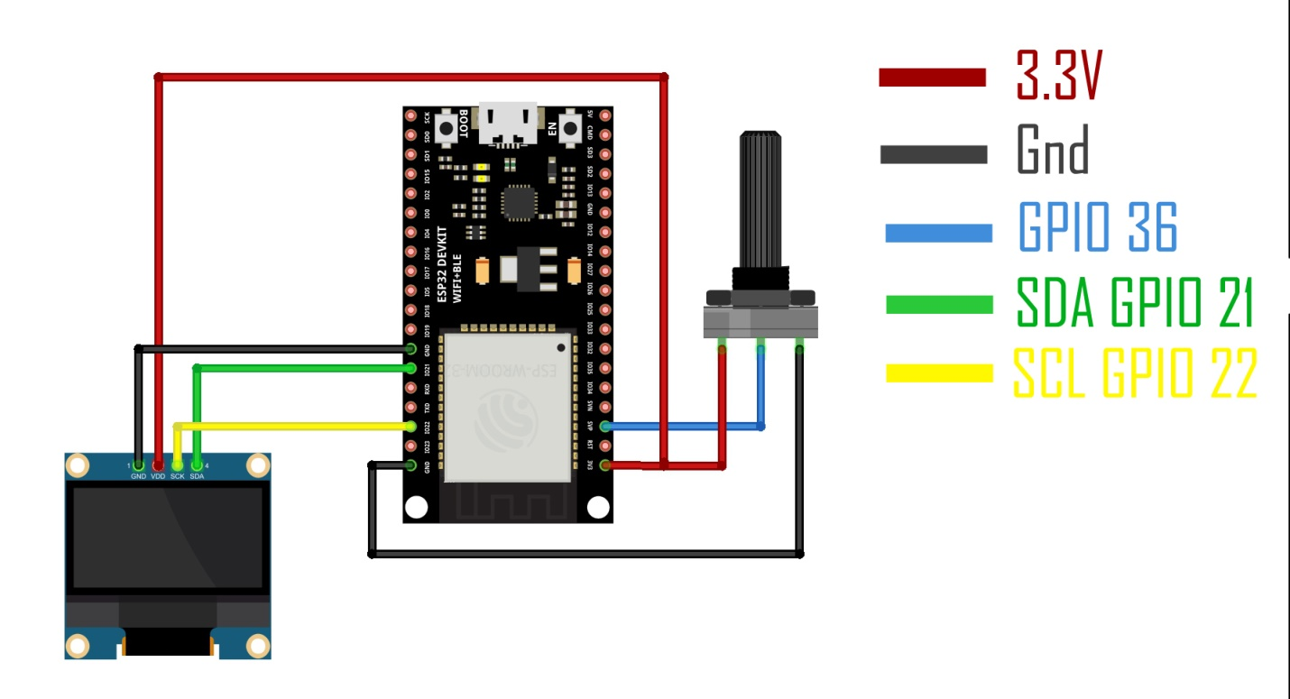
- -Connect one pin of the potentiometer with 3.3V of the ESP32
- -Connect the middle pin of the potentiometer with GPIO pin 36 of the ESP32
- -Connect the other pin of the potentiometer with the ground of the ESP32
- -Connect the VCC of the SSD1306 OLED display with 3.3V of the ESP32
- -Connect the Ground of the SSD1306 OLED display with the Ground of the ESP32
- -Connect the SDA pin of the SS1306 OLED display with GPIO pin 21 of the ESP32
- -Connect the SCL pin of the SS1306 OLED display with GPIO pin 22 of the ESP32
Required Libraries:
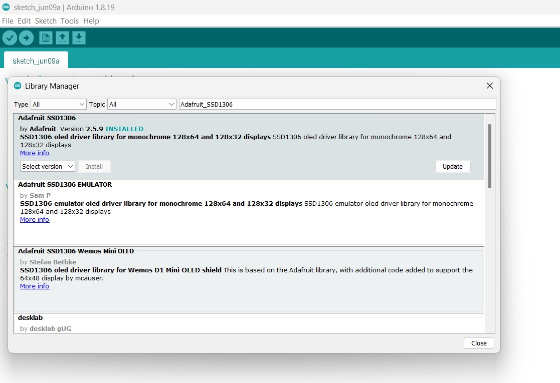
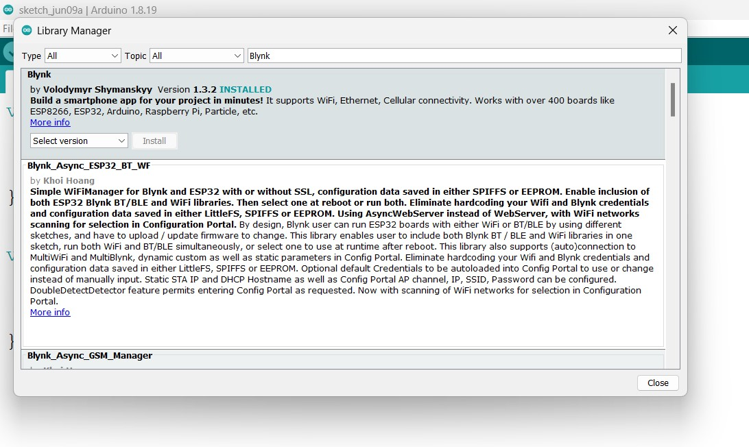
For the SSD1306 Oled display module, you will also need to install the Adafruit_GFX and Adafruit_SS1306 libraries. For this simply copy the Adafruit_GFX library name. Go to the Sketch menu > Include Library > Manage Libraries.
Paste the library name in the search box.
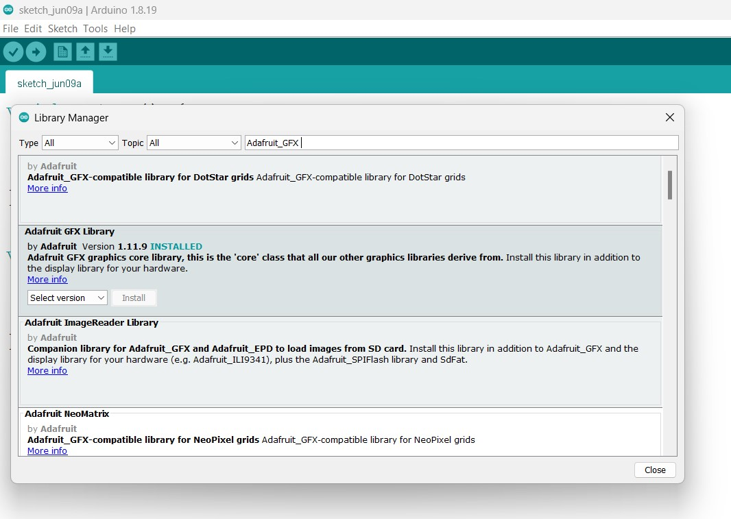
You can see, that I have already installed the Adafruit GFX library. Make sure, you also install the same library. Follow the same steps for the other library.
Similarly, for the SimpleTimer, install the Blynk library. We will also need the Blynk library for sending the sensor value to the Blynk IoT platform, which will be covered in this course.
ESP32 SSD1306 Oled Code:
#include
#include
#include
#include
#define REPORTING_PERIOD_MS 2000
SimpleTimer timer;
uint32_ttsLastReport = 0;
// for the OLED display
#define SCREEN_WIDTH 128 // OLED display width, in pixels
#define SCREEN_HEIGHT 64 // OLED display height, in pixels
// Declaration for an SSD1306 display connected to I2C (SDA, SCL pins)
#define OLED_RESET -1 // Reset pin # (or -1 if sharing Arduino reset pin)
Adafruit_SSD1306 display(SCREEN_WIDTH, SCREEN_HEIGHT, &Wire, OLED_RESET);
int Potentiometer = A0;
intPotVal = 0;
void setup()
{
Serial.begin(115200);
pinMode(Potentiometer,INPUT);
display.begin(SSD1306_SWITCHCAPVCC, 0x3C);
timer.setInterval(2000L, getSendData);
display.clearDisplay();
display.setTextColor(WHITE);
}
void loop()
{
timer.run(); // Initiates SimpleTimer
if (millis() - tsLastReport> REPORTING_PERIOD_MS) {
PotVal = analogRead(Potentiometer);
tsLastReport = millis();
}
}
voidgetSendData()
{
// Oled display
display.clearDisplay();
display.setTextSize(3);
display.setCursor(0,0); // column row
display.print("POT:");
display.setTextSize(4);
display.setCursor(0,30);
display.print(PotVal);
display.display();
}
6. I2C Liquid Crystal Display with ESP32:
Next, I am going to explain, how to interface and program an i2c supported 16x2 LCD. I personally recommend SSD1306. But, anyway, for the sake of this course, I have to cover it.
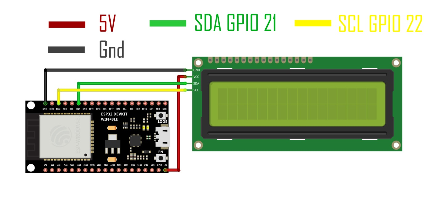
- -Connect the VCC pin of the I2C Liquid Crystal Display with 5V of the ESP32
- -Connect the Ground pin of the I2C Liquid Crystal Display with the Ground of the ESP32
- -Connect the SDA pin of the I2C Liquid Crystal Display with GPIO 21 of the ESP32
- -Connect the SCL pin of the I2C Liquid Crystal Display with GPIO 22 of the ESP32
ESP32 16x2 LCD Code:
#include
#include
LiquidCrystal_I2C lcd(0x27,16,2); //0x27 is the i2c address, while 16 = columns, and 2 = rows.
void setup() {
lcd.init(); //Init the LCD
lcd.backlight(); //Activate backlight
lcd.home();
}
void loop() {
lcd.clear();
lcd.print("electroniClinic");
delay(1000);
lcd.setCursor(0,1);
for (int i=0; i<=5; i++) //the columns are automatically incremented
{
lcd.print(i);
delay(500);
}
lcd.clear();
lcd.setCursor(0,0);
lcd.print("electroniClinic");
for (int i=0; i<=5; i++)
{
lcd.setCursor(0,1);
lcd.print(i);
delay(500);
}
lcd.noDisplay();
delay(500);
// Turn on the display:
lcd.display();
delay(500);
}
7. LDR and Relay Module with ESP32
Let’s make a simple yet highly useful project, a day and night detection system using an LDR sensor module and a 5V one-channel relay module. You know LDR is a light-dependent resistor which can be used for monitoring the light intensity. The LDR module I am going to use is capable of generating Analog and digital values. For this example, we are going to use the D0 which is the digital output. D0 pin gives 0 or 1 on the output based on the pre-set value which is set using the onboard potentiometer.
With the relay common and Normally Open you can connect a DC or AC load as per your preference. So, you can turn ON/OFF that specific load when the light or darkness is detected.
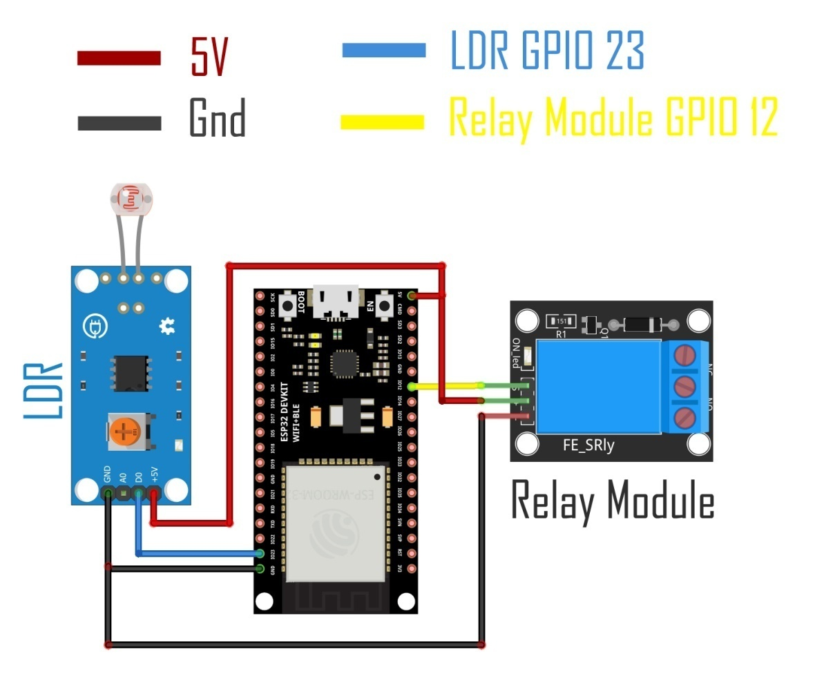
- -Connect the VCC pin of the LDR with 5V of the ESP32
- -Connect the Ground pin of the LDR with the ground pin of the ESP32
- -Connect the Signal pin of the LDR with GPIO pin 23 of the ESP32
- -Connect the VCC pin of the Relay module with 5V of the ESP32
- -Connect the Ground pin of the Relay module with the ground pin of the ESP32
- -Connect the relay module with GPIO pin 12 of the ESP32
Code:
int ldr = 23;
int relay = 12;
void setup() {
//Serial.begin(9600);
pinMode (ldr, INPUT);
pinMode (relay, OUTPUT);
}
void loop() {
if(digitalRead(ldr) == HIGH)
{
digitalWrite(relay, HIGH);
delay(3000);
}
if(digitalRead(ldr) == LOW)
{
digitalWrite(relay, LOW);
}
}
8. Ultrasonic sensor with ESP32
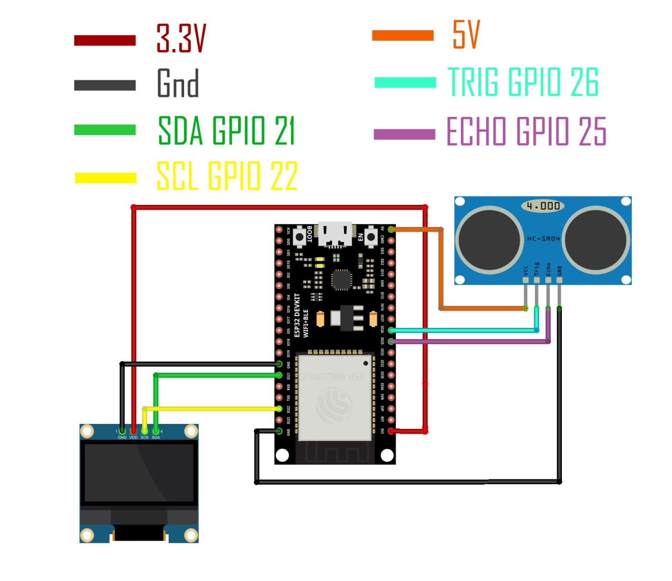
- -Connect the VCC of the SSD1306 OLED display with 3.3V of the ESP32
- -Connect the Ground of the SSD1306 OLED display with the Ground of the ESP32
- -Connect the SDA pin of the SS1306 OLED display with GPIO pin 21 of the ESP32
- -Connect the SCL pin of the SS1306 OLED display with GPIO pin 22 of the ESP32
- -Connect the VCC of the Ultrasonic sensor with 5V of the ESP32
- -Connect the Ground of the Ultrasonic sensor with the Ground of the ESP32
- -Connect the TRIG pin of the Ultrasonic sensor with GPIO pin 26 of the ESP32
- -Connect the ECHO pin of the Ultrasonic sensor with GPIO pin 25 of the ESP32
9. DHT21 Sensor with ESP32
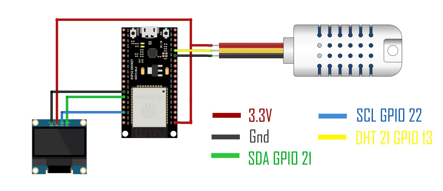
- -Connect the VCC of the SSD1306 OLED display with 3.3V of the ESP32
- -Connect the Ground of the SSD1306 OLED display with the Ground of the ESP32
- -Connect the SDA pin of the SS1306 OLED display with GPIO pin 21 of the ESP32
- -Connect the SCL pin of the SS1306 OLED display with GPIO pin 22 of the ESP32
- -Connect the VCC pin of the DHT21 sensor with the 3.3V pin of the ESP32
- -Connect the Ground pin of the DHT21 sensor with the Ground pin of the ESP32
- -Connect the signal pin of the DHT21 sensor with GPIO pin 13 of the ESP32
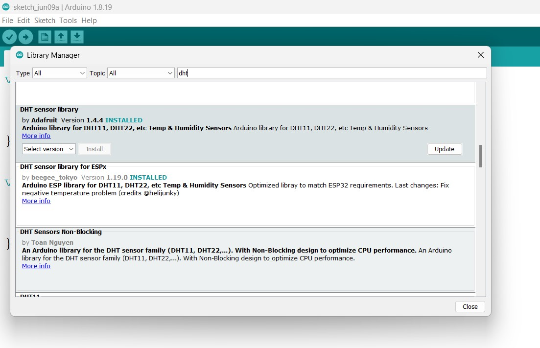
Required Library:
For this example, you will need to install the DHT library exactly the same way as we did for the Oled display module and the Blynk library.
DHT21 ESP32 Code:
#include
#include
#include
//Constants
#define DHTPIN 13 //what pin we're connected to
#define DHTTYPE DHT21 //DHT 21 (AM2301)
DHT dht(DHTPIN, DHTTYPE);
//Variables
float hum; //Stores humidity value
float temp; //Stores temperature value
#define SCREEN_WIDTH 128 // OLED display width, in pixels
#define SCREEN_HEIGHT 64 // OLED display height, in pixels
// Declaration for an SSD1306 display connected to I2C (SDA, SCL pins)
#define OLED_RESET -1 // Reset pin # (or -1 if sharing Arduino reset pin)
Adafruit_SSD1306 display(SCREEN_WIDTH, SCREEN_HEIGHT, &Wire, OLED_RESET);
void setup()
{
Serial.begin(9600);
dht.begin();
display.begin(SSD1306_SWITCHCAPVCC, 0x3C);
delay(2000);
display.clearDisplay();
display.setTextColor(WHITE);
delay(10);
}
void loop()
{
//Read data and store it to variables hum and temp
hum = dht.readHumidity();
temp= dht.readTemperature();
//Print temp and humidity values to serial monitor
Serial.print("Humidity: ");
Serial.print(hum);
Serial.print("%, Temperature: ");
Serial.print(temp);
Serial.println(" Celsius");
display.clearDisplay();
display.setTextSize(2);
display.setCursor(0, 10);
display.print(temp);
display.print((char)247);
display.print("C");
display.setTextSize(2);
display.setCursor(0, 30);
display.print("H:"+String(hum)+"%");
display.display();
}
10. Blynk with ESP32
In this example, we are going to monitor the DS18B20 waterproof one-wire digital temperature sensor using the Blynk IoT platform. We will not only monitor the temperature but we will also control a relay.
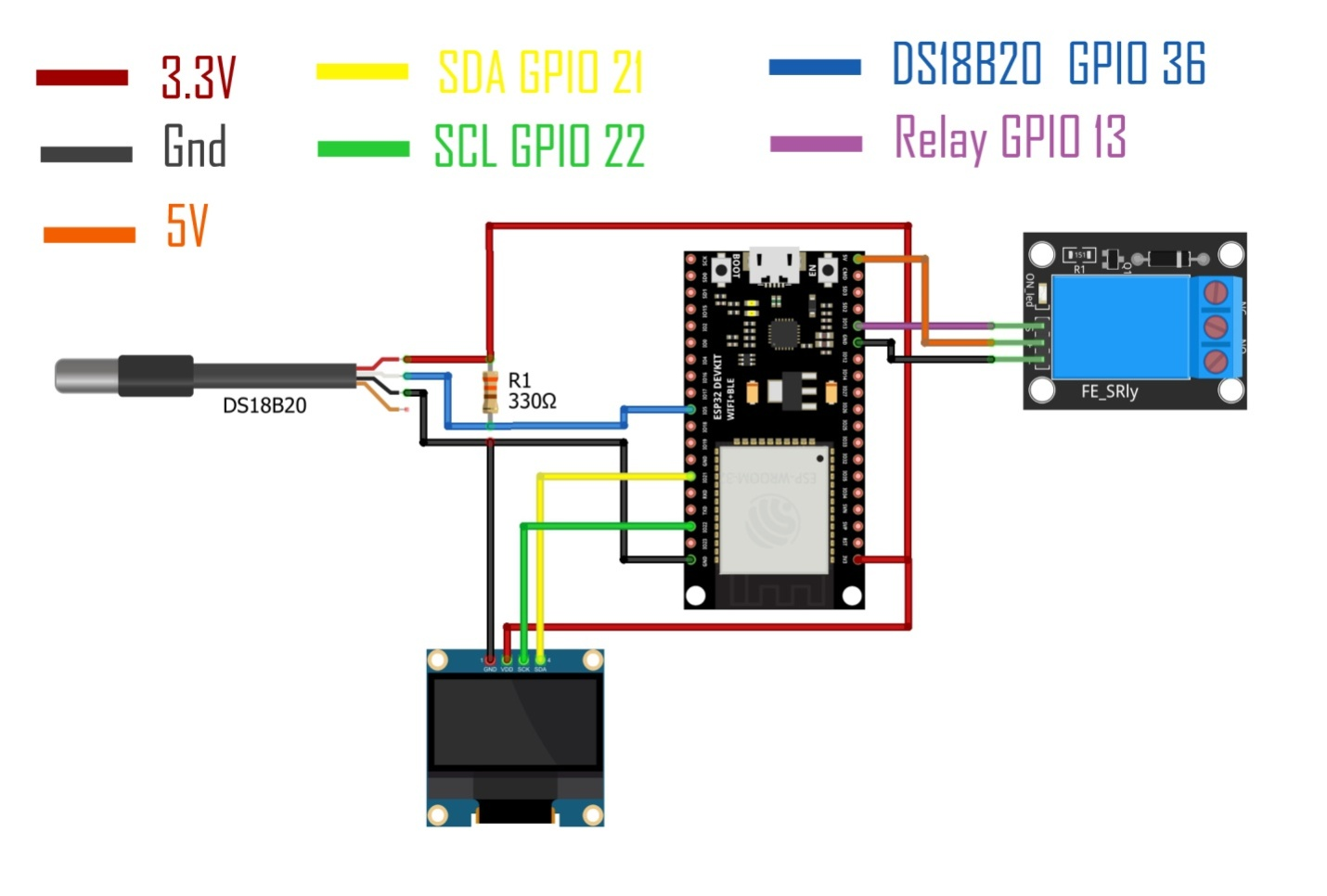
- -Connect the VCC of the SSD1306 OLED display with 3.3V of the ESP32
- -Connect the Ground of the SSD1306 OLED display with the Ground of the ESP32
- -Connect the SDA pin of the SS1306 OLED display with GPIO pin 21 of the ESP32
- -Connect the SCL pin of the SS1306 OLED display with GPIO pin 22 of the ESP32
- -Connect the VCC pin of the DS18B20 with 3.3V of the ESP32
- -Connect the Ground pin of the DS18B20 with the Ground pin of the ESP32
- -Connect the signal wire of the DS18B20 with the GPIO 5 pin of the ESP32
- -Connect the VCC of the relay module with 5V of the ESP32
- -Connect the Ground of the relay module with the Ground of the ESP32
- -Connect the signal pin of the relay module with GPIO13 of the ESP32
Web dashboard in Blynk IO:
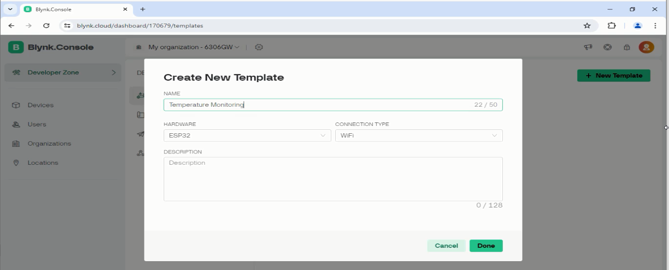
First, you need to make a free Blynk account.
Login into your Blynk account.
Click on the new template, give a name to the template, and then click on the done button
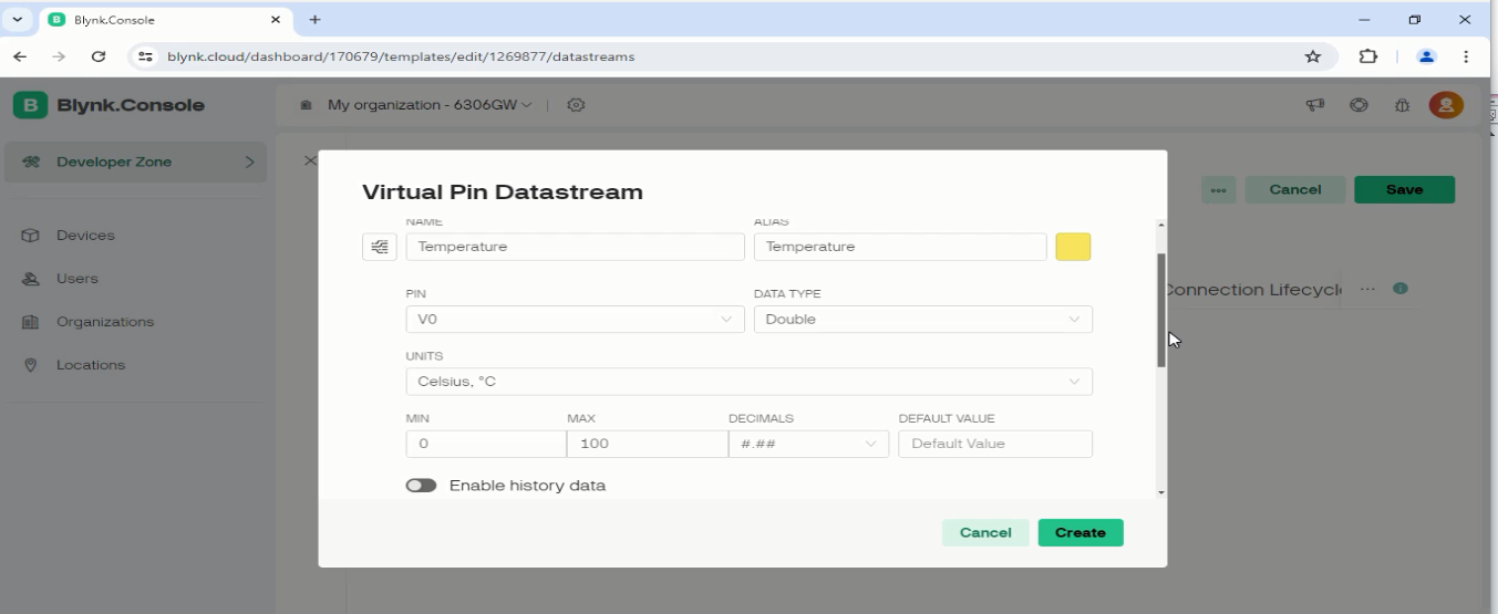
Next, on the Datastreams Tab, click on the New Datastream, and select Virtual Pin.
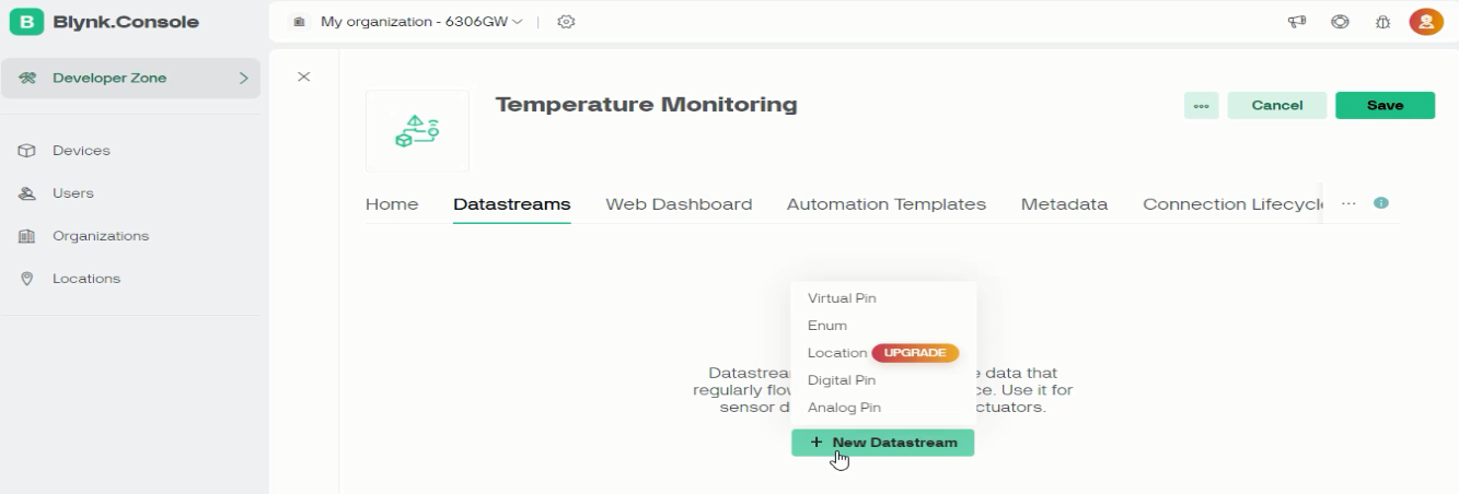
Write the name, select the virtual pin “V0”, select the Data Type, select the MIN and MAX values, and then finally click on the Create button.
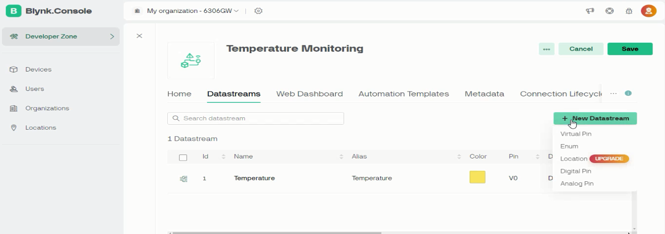
We will also need a virtual pin for the Relay module. So, again click on the New Datastream, and select Virtual Pin.
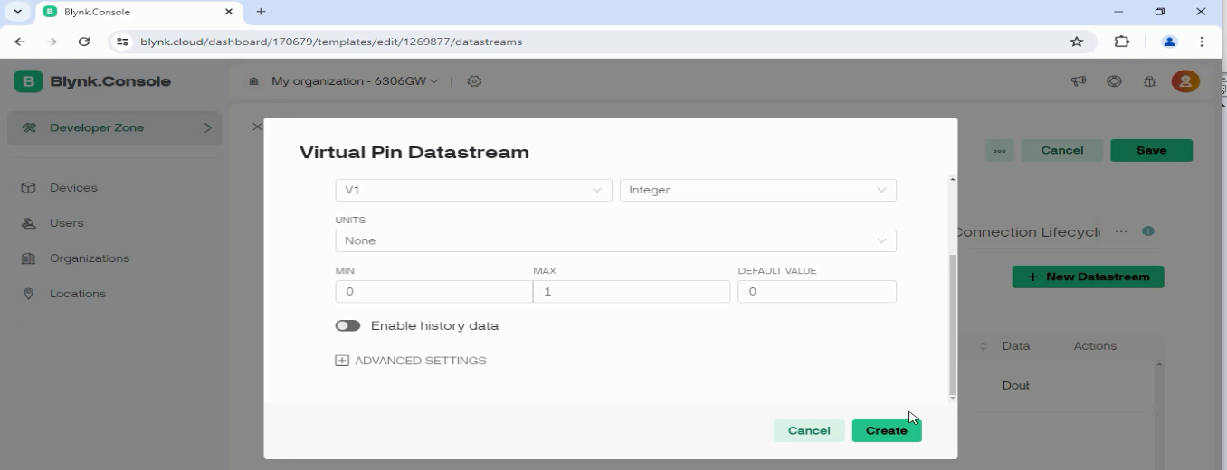
This time we are going to select V1, data type as integer, and we are going to select 0 as the MIN and 1 as the MAX. 0 means to turn OFF the relay and 1 means to turn ON the relay.
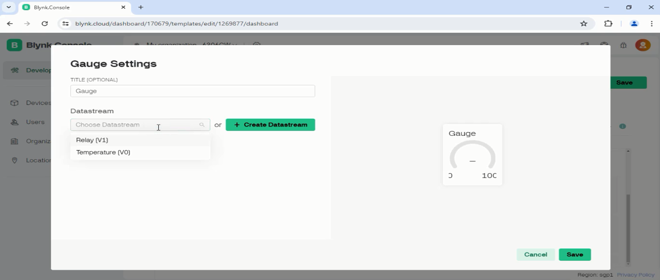
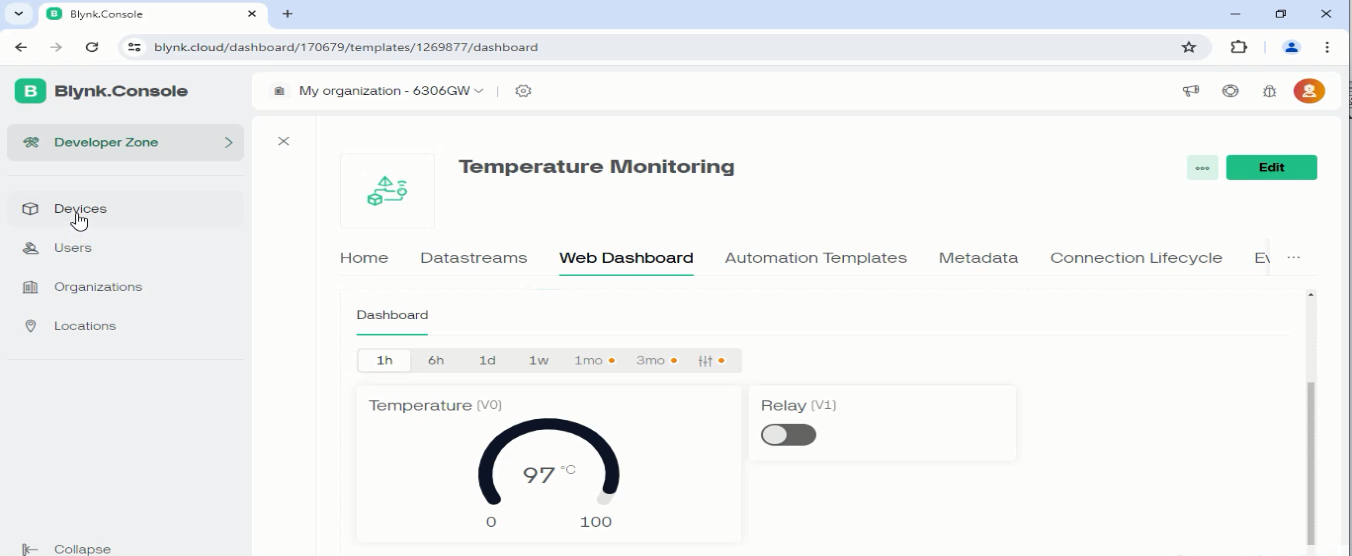
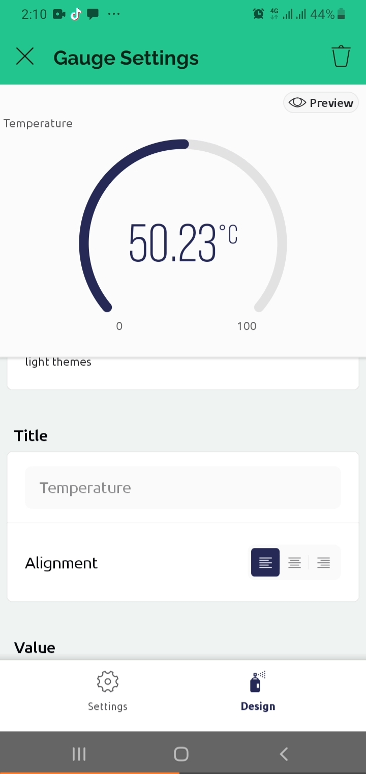
Now click on the Web Dashboard Tab and add a gauge for monitoring the temperature. Click on the Gear Icon to open the gauge setting
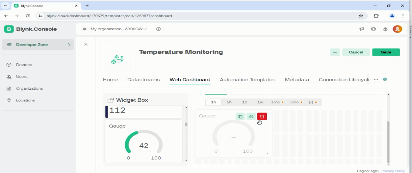
Link the Datastream V0 to the Gauge and click on the Save button.
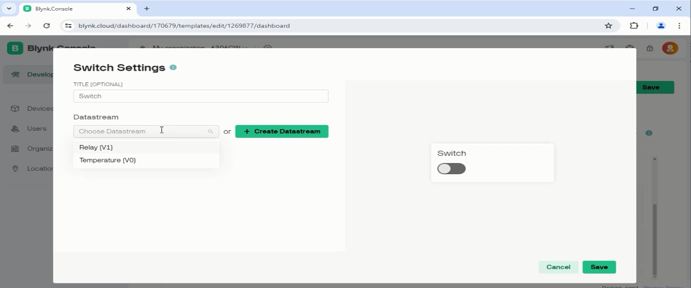
Repeat the same steps for a switch.
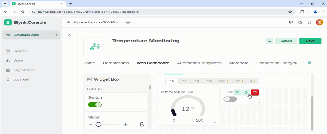
Link its Datastream to the switch.
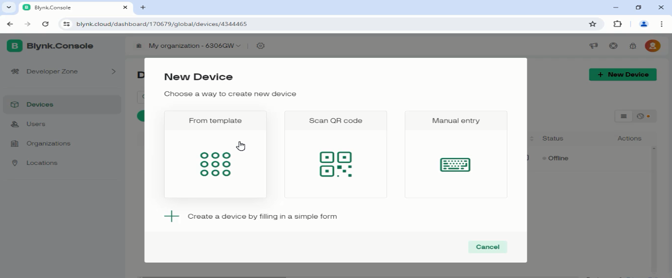
Click on the Devices.
Click on the new device and select from the template.
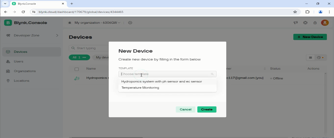
Choose the template “Temperature Monitoring” and click the create button.
Copy the New Device credentials.
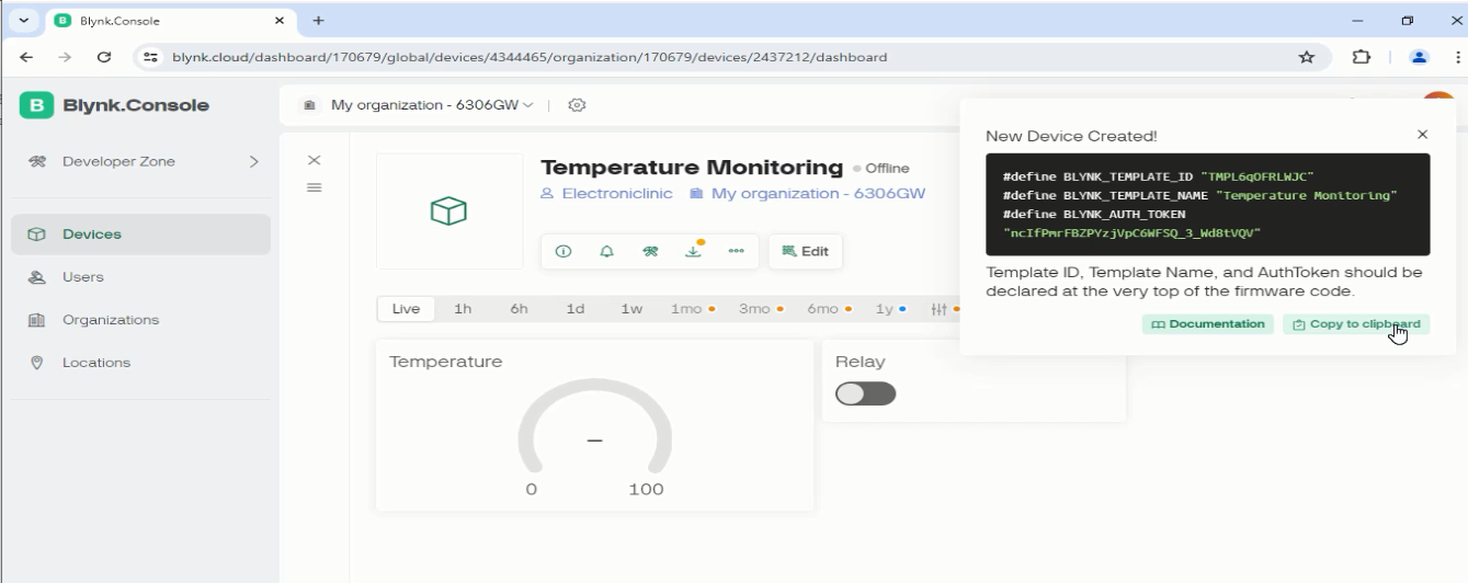
Paste these credentials in the code.
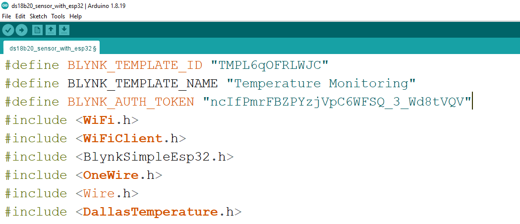
ESP32 and Blynk Program:
#define BLYNK_TEMPLATE_ID "TMPL6qOFRLWJC"
#define BLYNK_TEMPLATE_NAME "Temperature Monitoring"
#define BLYNK_AUTH_TOKEN "ncIfPmrFBZPYzjVpC6WFSQ_3_Wd8tVQV"
#include
#include
#include
#include
#include
#include
#include
#include
#include
char auth[] = BLYNK_AUTH_TOKEN;
// Your WiFi credentials.
// Set password to "" for open networks.
char ssid[] = "AndroidAP3DEC";
char pass[] = "electroniclinic";
int Relay = 13;
SimpleTimer timer;
#define SCREEN_WIDTH 128 // OLED display width, in pixels
#define SCREEN_HEIGHT 64 // OLED display height, in pixels
// Declaration for an SSD1306 display connected to I2C (SDA, SCL pins)
#define OLED_RESET -1 // Reset pin # (or -1 if sharing Arduino reset pin)
Adafruit_SSD1306 display(SCREEN_WIDTH, SCREEN_HEIGHT, &Wire, OLED_RESET);
namespace pin {
const byte one_wire_bus = 5; // Dallas Temperature Sensor
}
namespace sensor {
float waterTemp = 0;
}
OneWire oneWire(pin::one_wire_bus);
DallasTemperature dallasTemperature(&oneWire);
void setup() {
Serial.begin(115200); // Dubugging on hardware Serial 0
dallasTemperature.begin();
Blynk.begin(auth, ssid, pass);
display.begin(SSD1306_SWITCHCAPVCC, 0x3C);
delay(2000);
display.clearDisplay();
display.setTextColor(WHITE);
pinMode(Relay,OUTPUT);
digitalWrite(Relay,LOW);
timer.setInterval(1000L, displayValue);
}
void loop() {
Blynk.run();
timer.run(); // Initiates SimpleTimer
}
void displayValue()
{
dallasTemperature.requestTemperatures();
sensor::waterTemp = dallasTemperature.getTempCByIndex(0);
Serial.print(F("Temperature:")); Serial.println(sensor::waterTemp,2);
display.clearDisplay();
display.clearDisplay();
display.setTextSize(2);
display.setCursor(0, 10);
display.print(sensor::waterTemp);
display.print((char)247);
display.print("C");
display.display();
Blynk.virtualWrite(V0, sensor::waterTemp);
}
BLYNK_WRITE(V1)
{
int pinValue=param.asInt();
digitalWrite(Relay,pinValue);
}
Mobile Dashboard in Blynk IO:
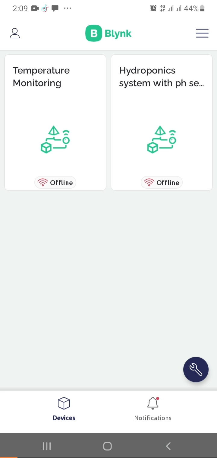
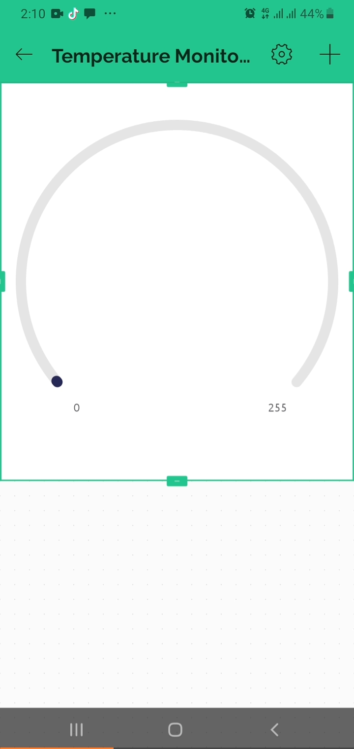
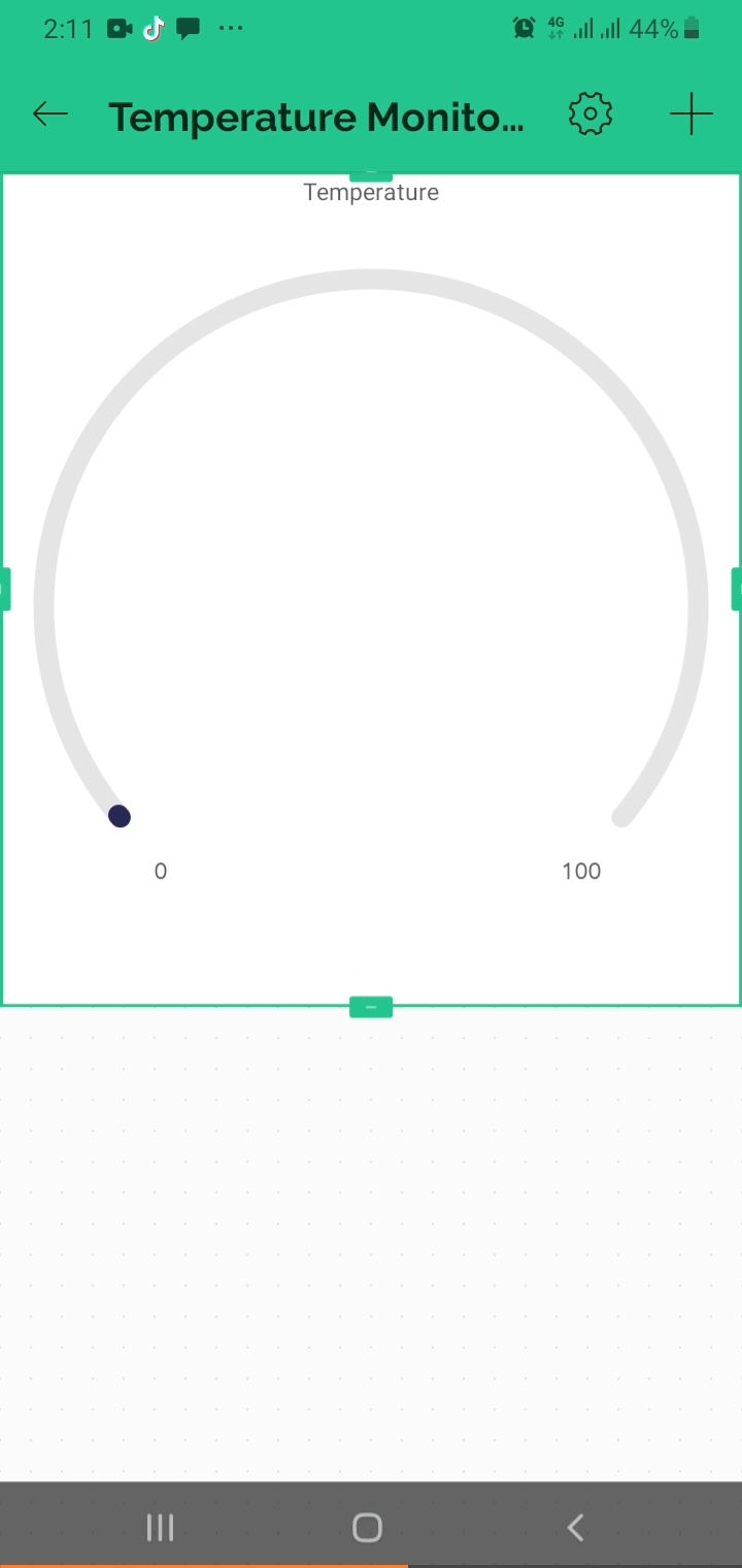
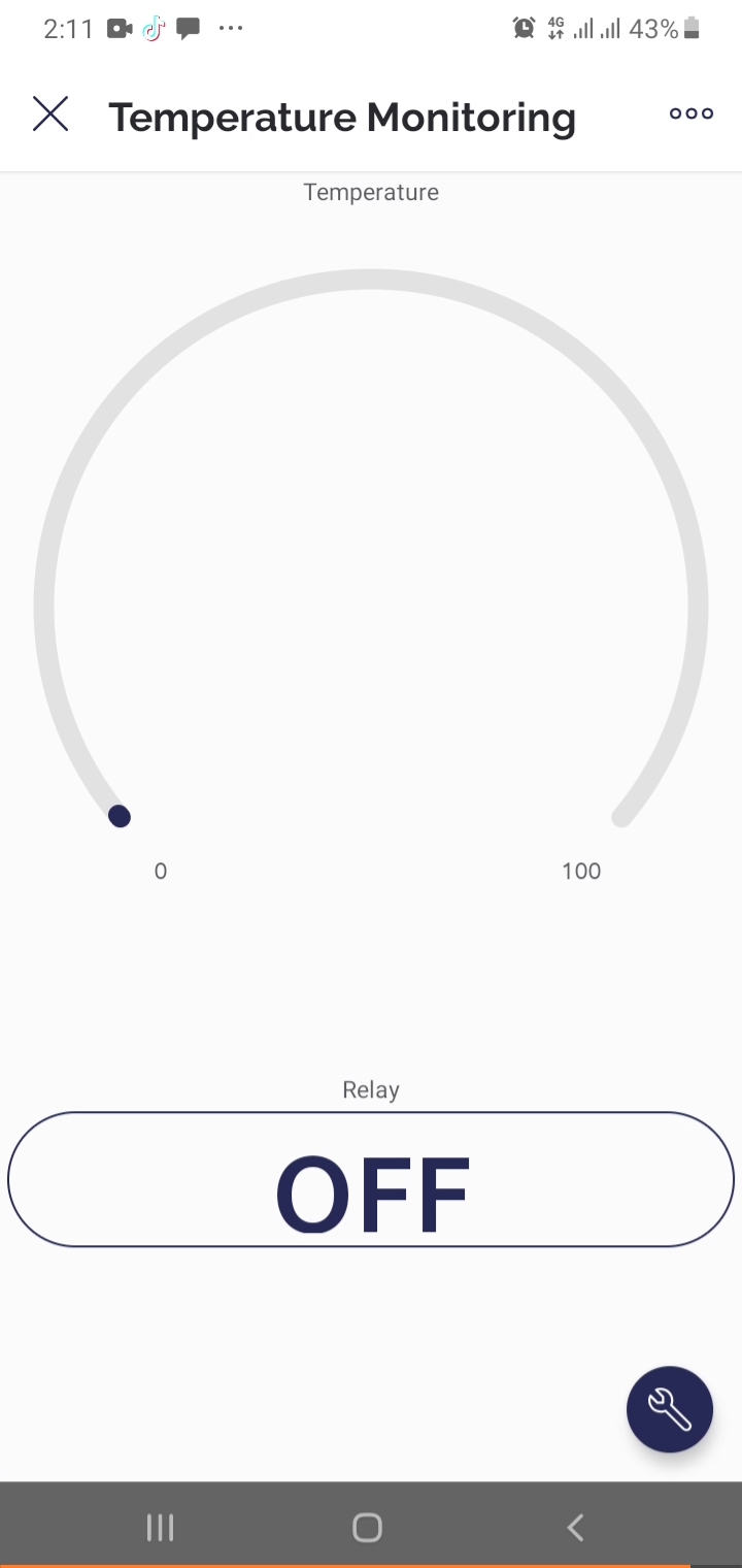
Open the Blynk IoT App in mobile and select the temperature monitoring project.
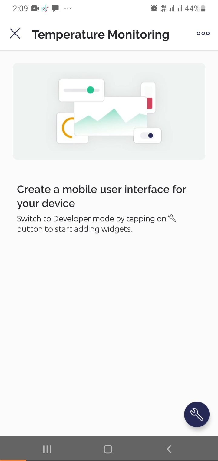
Then click on setting to enter in the developer mode.
Then click on the plus sign and add a Gauge
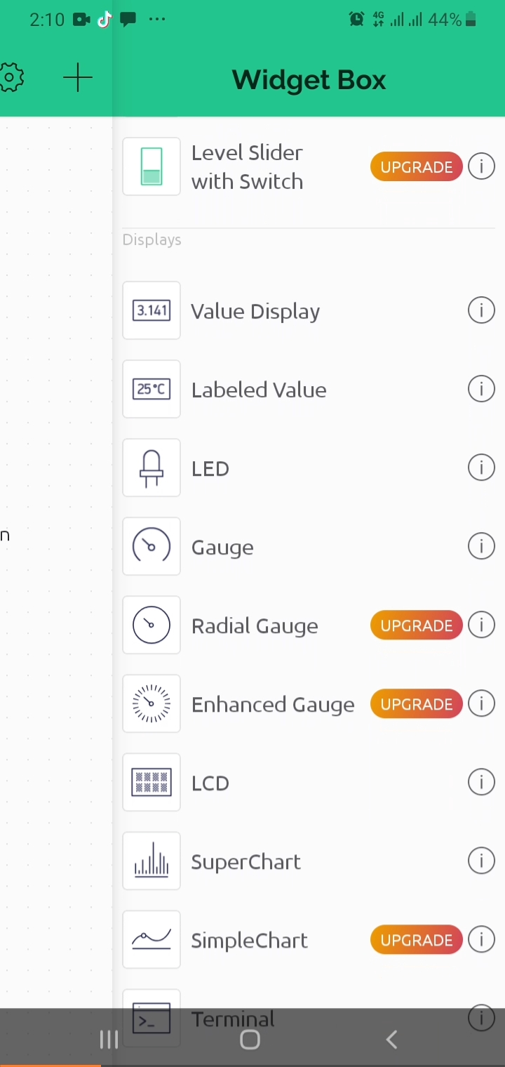
Then click on the gauge
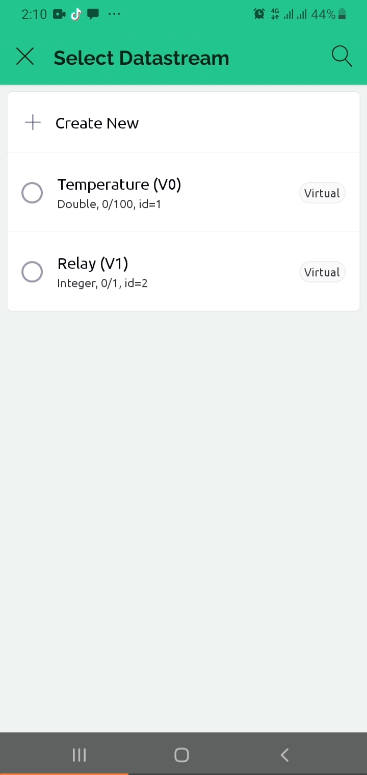
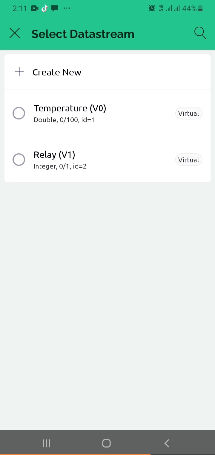
Now select the Datastream
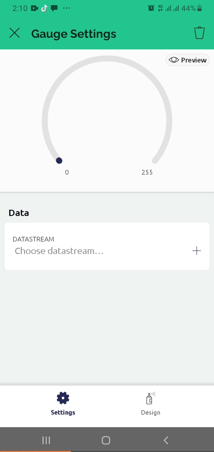
Select the desired Datastream.
Then click on the Design to adjust the text size
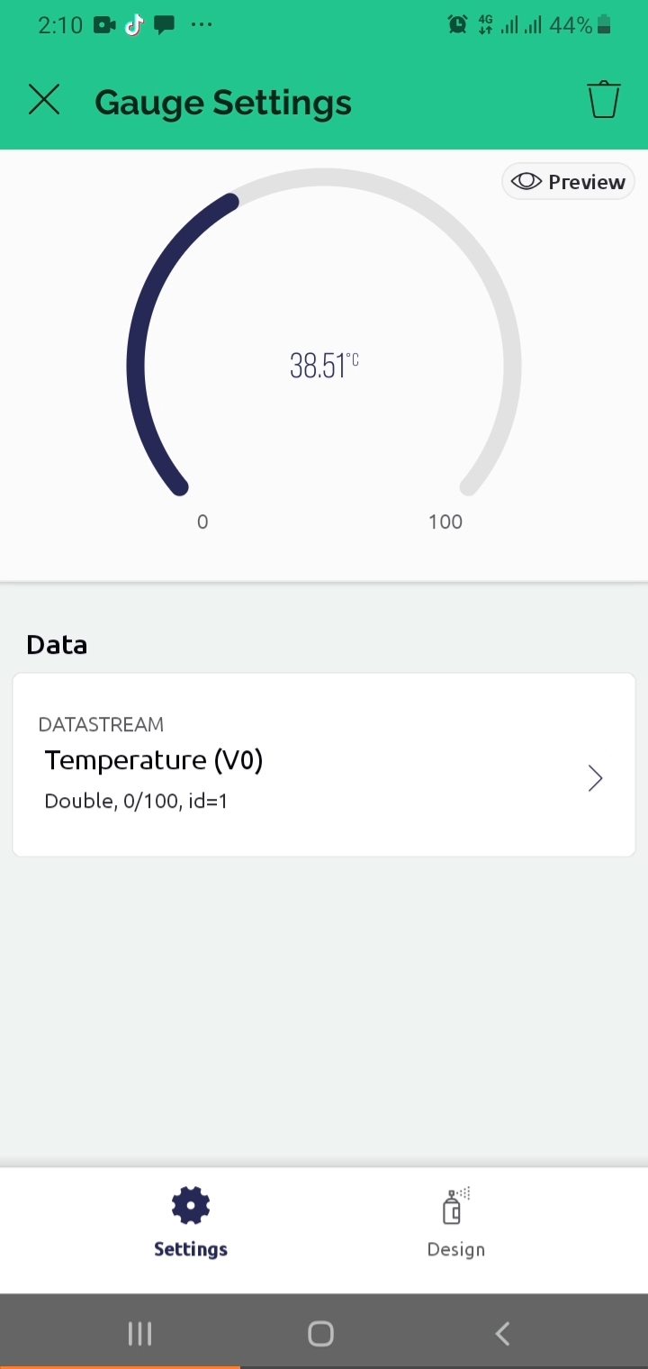
Then give a title to the Gauge.
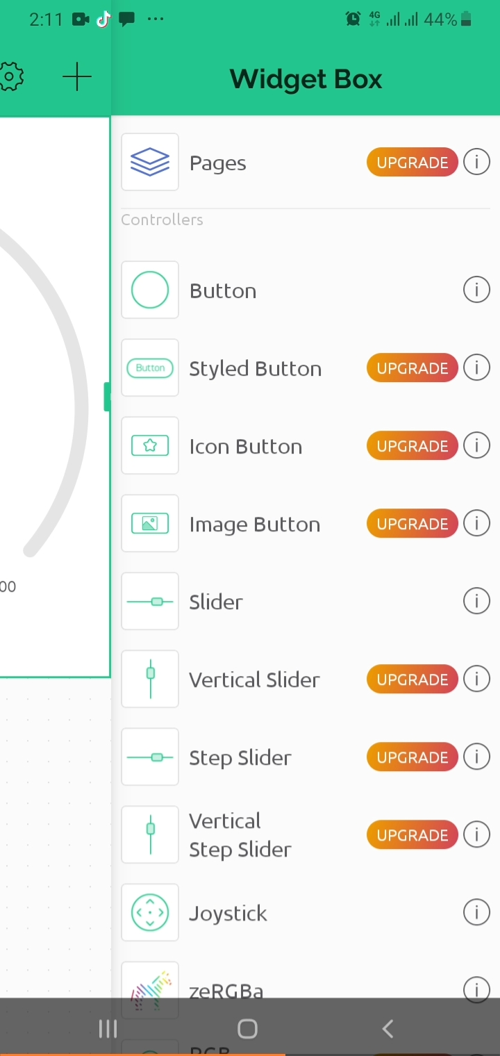
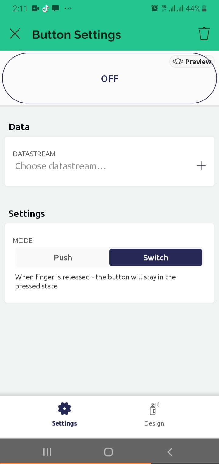
Now click on the “+” sign to add the button
Select a Button from the list
Then click on the button
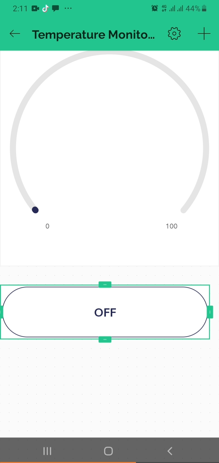
Select the Datastream and change its mode to switch.
Select its Datastream
The Blynk IoT application is ready.
Comment