The 4017 decade counter integrated circuit is a wonderful chip for creating fun and mesmerizing LED light chaser projects. You can design all sorts of dazzling lighting effects by using a 4017 IC, some LEDs, and basic electronic components.
In this article, I will explain how the popular 4017 IC works and then proceed to provide instructions for building LED chaser circuits. By the end of the article, you should know how to create impressive light shows with these designs, whether for beautifying your house or enlightening others with your creations. 4017 IC circuits mark the beginning of a new world of creative LED light signage.
Let's get started by taking a closer look at what makes the 4017 IC so well-suited for chaser applications.
The 4017 IC Decade Counter Explained
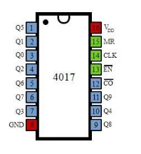
The 4017 IC is a decade counter, which means that this chip can count in tens. It counts from 0-9 and then returns to 0, repeating the sequence. It has 10 output pins labeled Q0 – Q9, corresponding to the values that the counter is counting. Only one output will be active "high" at a time as the IC internally increments through its counting sequence.
There are flip-flops in the 4017 IC each of which is connected sequentially. A flip-flop is a basic digital circuit for storing binary information in that it holds 2 states – in this case, a 1 or 0. It can be controlled to sequence through its output pins in a linear order, thereby replicating the role of a decade counter by properly toggling the flip-flops in a given order.
A control signal is fed into one of the 4017's four input pins labeled CT (Count), CLK (Clock), MR (Mode Reset), and G (Gate) to drive the counting process:
- CT/CLK: A rising edge on this pin causes the counter to increment to the next number. It functions as both the Count and Clock input.
- MR: When held low, the 4017 will continually count from 0 to 9. When taken high, it resets the counter back to 0.
- G: When held low, the counting process is enabled. Taking it high inhibits any counting action.
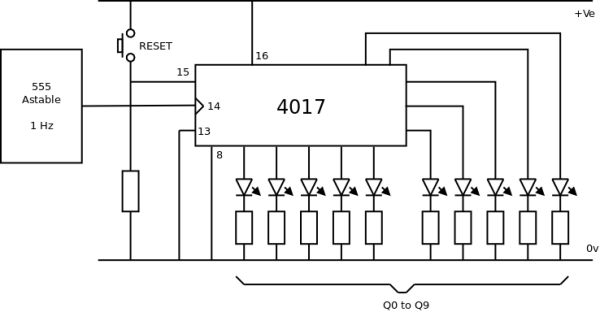
By pulsing the CT/CLK pin at a constant rate, the 4017 increments through its outputs, sequentially turning each pin on for a brief period before the next takes over. This generates the repetitive counting sequence needed for an LED chaser effect.
Connecting LEDs to each output pin means that as the 4017 internally steps through 0-9, it will externally light up the LEDs in a left-to-right "chasing" pattern. Add some basic timing components to control the clock pulse frequency, and you have the heartbeat of an LED chaser circuit.
Building a Basic LED Chaser
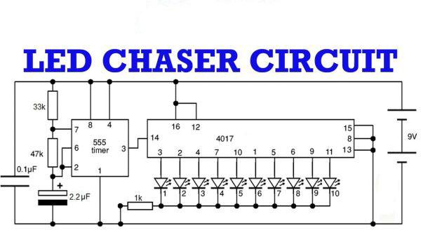
Now that the 4017 decade counter is explained, let's jump into an example of putting it to use in an LED chaser project. One of the simplest versions uses just a 4017, LEDs, resistors, a battery, and a capacitor for clock timing.
Here are the components you'll need:
- 1 x 4017 IC
- 10 x LEDs (any color)
- 10 x 220 ohm resistors
- 1 x Battery (3V or higher)
- 1 x 0.01uF capacitor
- Breadboard
- Jumper wires
Follow these steps to build it:
- Place the 4017 IC into your breadboard with its notch facing the left side. Make sure the IC is resting entirely within the breadboard - no pins should hang off the edges.
- Connect the cathode (short lead) of each LED to one of the 4017's output pins from Q0 to Q9. Make sure to use a separate 220-ohm resistor in series with each LED connection.
- Connect all the LED anodes (long leads) to the positive side of your battery.
- Connect the negative battery terminal to the 4017's GND pin.
- Connect one side of the 0.01uF capacitor to the CT/CLK pin of the 4017. Connect the other side to the positive voltage rail.
- Connect the positive voltage rail/battery to the 4017's VCC pin.
- Leave the MR pin unconnected so it defaults to continually counting mode.
That's it! You've just built your first LED chaser circuit. Plug in the battery and watch as the LEDs light up one after another like dominoes falling over. Adjusting the size of the timing capacitor will alter the speed of the chase effect.
This demonstrates the essence of using a 4017 IC - by sequentially toggling its outputs, you can create a linear chasing pattern of lights. From here, we can expand on the concept to produce more interesting visual sequences.
More Complex Chase Patterns
Building off the basic chaser template established above, we can modify the connections to achieve other types of repeating LED patterns beyond a simple left-to-right march. Here are a few variations to try:
Bounce Chaser
To create a "bouncing" chase effect rather than a straight linear, wire the LEDs in a zig-zag formation rather than side by side. For example, connect the odd outputs (Q1, Q3, etc.) first in one row, then the even outputs (Q0, Q2, etc.) in the row above or below. Now the light chase will bounce back and forth between the LED banks.
Random Chaser
Add randomness and unpredictability to the sequence by switching the order of the LED connections to the 4017 outputs. Mix up where each LED is attached - the chase pattern will appear to move at random rather than following a strict left-to-right progression.
Ping Pong Chaser
Achieve a two-way ping pong chase by splitting the 10 LEDs into two parallel strings of 5. Wire the first 5 LEDs to outputs Q0 through Q4, and the second 5 LEDs to the reverse outputs Q9 through Q5. Now the chase will continuously bounce back and forth between the two LED banks.
Rainbow Chaser
For a colorful multi-colored chase, group the LEDs by color - connect 3 red, 3 green, 2 blue, and 2 yellow in whatever pattern you like. Now the sequence takes on a rainbow-esque quality as it marches through the differently-hued bulbs. Get creative with your color combinations!
There are limitless ways to configure the connections to produce unique lighting sequences. Experiment with different LED arrangements and observe how even subtle changes in wiring produce noticeably altered chaser styles.
External Controls
So far we've relied on the internal counting behavior of the 4017 IC to run autonomously once powered on. But we can introduce more dynamic control by accessing the 4017's input pins. Adding external buttons or switches gives real-time control over the chase effect.
Here are some examples:
Reset Switch
Connect a switch between the 4017's MR pin and ground. Pressing it will manually reset the counter back to the start rather than waiting for it to naturally roll over. This staggers the sequence.
Speed Control
Add a potentiometer wired as a voltage divider between the power and the CT/CLK pin. Turning the knob varies the clock pulse frequency to speed up or slow down the chase rate in real-time.
Direction Switch
Wire two switches - one between MR and ground, one between MR and power. Each switch press toggles the reset pin to change the counting direction from up to down or vice versa.
Run/Stop Switch
Connect a switch between the 4017's G pin and ground. When closed it allows counting, when open it pauses the effect by inhibiting the clock pulses. Manually start/stop the sequence.
These are just a few simple ways to introduce manual overrides so the LED patterns can be conveniently manipulated on command. Any switches, knobs, or buttons can bring new interaction possibilities to 4017 chaser creations.
DIY Components
So far we've stuck to pre-assembled basic electronic parts. However, you don't need to buy anything special - many components used in 4017 LED chaser circuits can be easily fabricated at home from common materials. Here are some examples of DIY alternatives:
Resistors - For low-power LED applications, use short lengths of different thickness wire or stripped strands of hook-up wire to achieve resistor values. Thicker wire equals lower resistance.
Timing Capacitor - Roll up a small piece of aluminum foil then sandwich it between two pieces of cardboard for an impromptu capacitor. The tighter the wrap, the lower the capacitance.
Breadboard - Create a prototype area by sticking strips of copper tape, conductive fabric like aluminum foil, or bare wires onto cardboard, plastic, or even LEGO bricks.
Power Supply - Two or three AA/AAA batteries tapped together in series provide 3-5V. Rechargeables allow portable projects.
Enclosures - Convert plastic containers, boxes, or even sockets into protective casings—drill holes for components and wires.
LEDs - Even find small high-brightness LEDs from unwanted electronics like remote controls or pulled from flashlight bulbs.
While simpler parts may only last for a short time, prototyping with homemade substitutes allows chaser creations on any budget using materials already on hand. And there's a satisfaction that comes from building entirely from scratch.
Advanced 4017 Circuits
Once you've exhausted the basic sequencing possibilities with a single 4017 chip, it's time to scale things up by linking multiple counters together. Combining 4017 ICs introduces exponentially more complex LED patterns and light shows.
Here are a few advanced multi-chip designs to experiment with:
Layered Chase
Build two identical basic chaser circuits but have the second string of LEDs offset by one connection (Q0 connects to Q1 instead of Q0, etc). When powered, they interact to produce an illusion of depth with overlapped chases.
Snake Chase
Connect the Q9 output of one 4017 directly back to the reset pin of a second 4017 whose LED string is wired in parallel. Their combined sequential movements resemble an endless S-pattern snake. Add more chips for longer snakes.
Matrix Chaser
Lay out a grid of LEDs and wire each row/column to a separate 4017. Their coordinated outputs allow the lighting of any pixel in complex animations across the matrix. Digital multiplexing achieves passive grid sizes.
Expanding beyond a single chip opens the door to much larger exhibitions of light with deep complexities only revealed through their choreographed dances. Additional components bring new life to 4017 compositions.
Example Components:
- Transistors - Boost current capabilities for higher-powered LEDs
- Timers - Introduce randomized/timed events
- Sensors - React to environmental inputs
- Microcontrollers - Add programmed logic & behaviors
Combining 4017 logic sequencing, user interaction, and environmental inputs with display elements creates chaser systems that are more like living light sculptures. The possibilities seem endless once you start integrating the 4017 concept into more robust electronic designs.
Modular & Expandable Creations
A major advantage of building 4017 circuits is how their modular, scalable nature lends itself to ongoing expansion and customization. Projects grow organically as ideas build upon ideas. Here are some ways to evolve designs incrementally:
Increase LED Count - Simply add extra LEDs, resistors, and breadboard connections to enlarge existing patterns.
Cascade More Chips - Link 4017 ICs together for expanded timing sequences over larger scales.
Add Color Variety - Replace monochrome LEDs with RGB/RGBW types for full-spectrum effects.
Branch Out Effects - Integrate components like motors, servos, or output triggers to drive auxiliary actions.
Create Coded Modules - Develop interconnect "node" boards with I/O standardized for mixing into arrangements.
Integrate Sensors/Inputs - React to environmental or user stimuli like sound, light, and buttons for dynamic response.
Switch Display Surfaces - Mount LEDs or full modules on different items like clothing, household objects, or public installations.
Modular construction lets exhibits take on a life of their own as sections are swapped in/out or recombined in new layouts. The final results become shapeshifting expressions that continue evolving with each iteration. 4017 circuits beautifully exemplify iterative prototyping through continuous expansion.
4017 Projects to Inspire You
By now hopefully, you have a solid understanding of the 4017 IC and creativity flowing with ideas for your own dazzling LED chaser creations. But it's also valuable to see the innovation of other builders for extra doses of inspiration.
Here are a few impressive 4017 projects for consideration in your work:
Motion-Activated LED Sculpture - LED strips wrapped various found objects activated by passive infrared sensor to undulate with passerby movements.
Geometric Light Tunnel - Dozens of RGBW LED panels connect as facades of a long cylindrical column whose sequenced synchrony craft compelling interior spectacle.
Reactive Light Graffiti - 4017 modules hot-glued as mural elements respond to changing color/patterns reacting to live music/audio levels in a profound audiovisual experience.
Architectural Accents - Flashing neon-style LED signs outline buildings' rooftop cornices or accent glass railings in cascading light showing visible blocks away at night.
Festive Holiday Décor - Color-changing Christmas tree lights, icicle lights, or projected light displays bring magic to seasonal celebrations.
Collaborative Light Paintings - Artists mount addressable RGB panels as "pixels" on a large wall-mounted "canvas" remotely controlled over a network for live, interactive light art.
Smart LED Garland - Modular chaser/sensor modules daisy-chained as wearable festoons or wrapped objects like trees or bikes dynamically reacting to movement through IR proximity sensing.
Wearable Accessories - Battery-powered fashion accessories like LED bracelets, necklaces, hats, or clothing accents with built-in 4017 logic circuits for illuminated personal displays.
Even drawing inspiration from other fields can spark applications beyond traditional static holiday lights. Imagine how principles might translate for informative/interactive museum exhibits, commercial signage, carnival game displays, and more...the chip unleashes a creative light engineer within us all.
Final Thoughts
With just a basic understanding of the 4017 integrated circuits and some fundamental electronic skills, you can assemble delightful LED chaser projects capable of producing truly mesmerizing shows of cascading light. But their potential goes far beyond mere entertainment - these principles translate across lighting, displays, art and so much more.
Through continued experimentation by cascading additional 4017 chips, integrating new components, scaling across larger expanses, and building modularly, your chaser creations will evolve like dynamic light sculptures responding to your inspiration.
I hope this article has unlocked a new door of possibilities and creativity for you to step through on your light engineering adventures. By getting familiar with the language of light through chasing LED sequences, you are well on your way to developing stunning displays capable of bringing smiles, wonderment, and positivity through dazzling illuminated expressions. Now go forth to shine your works bright for all to enjoy!
Comment