Hello friends, I hope you all are doing great. Welcome to another exciting project in the ESP32 learning series. In today’s tutorial, we will design a Smart Bank Security System using ESP32.
The evolution of IoT has improved the security systems manifolds. Modern security systems have real-time communication with the servers and upload sensitive data to the cloud. It enables the security personnel to constantly monitor and act immediately in case of any breach.
We can use different IoT modules for designing security systems i.e. Raspberry Pi, STM32, ESP32, BeagleBone etc. For today’s project, we are going to use an ESP32 Microcontroller board to provide WiFi capability to our project.
Components Free Worldwide Shipping
Project Overview/Working
Here’s the final output of today’s project i.e. Smart Bank Security System using ESP32:
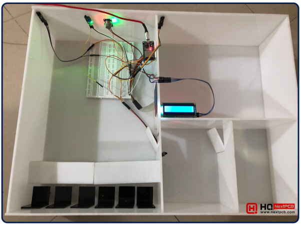
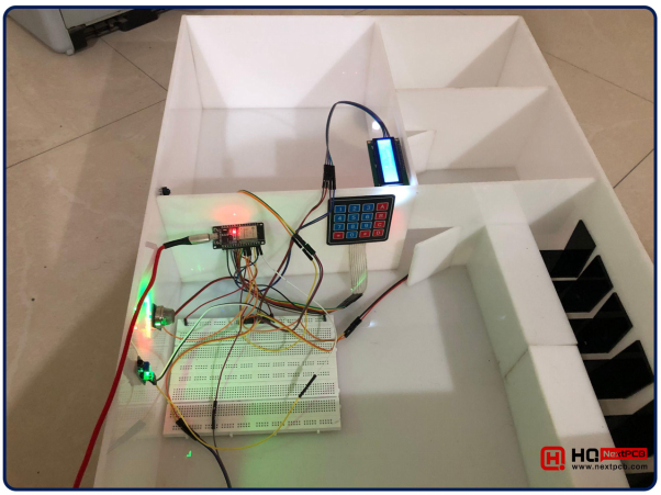
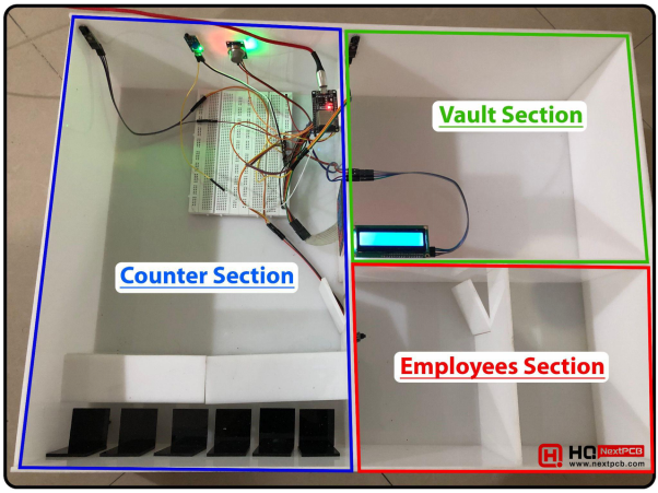
As you can see in the above figure, we have designed a Bank model using acrylic sheets. This model will have 3 sections named:
- Counter Section: To handle Bank Customers.
- Employees Section: For Bank Employees.
- Vault Section: A highly secured Bank Vault to protect the money.
In the below figure, I have labelled these 3 sections:
Based on the functionality of these sections, we have added 2 modes in our project, named:
- Day Mode: In this mode, the Counter & Employees section will operate normally i.e. people can enter/leave these premises, while the vault section will be highly secured and only authorized persons with the PinCode will be allowed to enter.
- Night Mode: In this mode, all 3 sections will be completely secured and authorities will be alerted if any unauthorized entry is detected.
Security Sensors
We have used the below 5 sensors to secure our Bank:
- Fire Sensor: To detect the fire.
- Smoke Sensor: To detect the smoke.
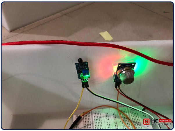
- Vault IR Sensor: To detect unauthorized entry in the Vault.
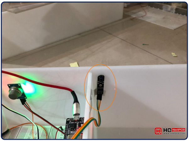
- Employee IR Sensor: To detect unauthorized entry in the Employee Section.
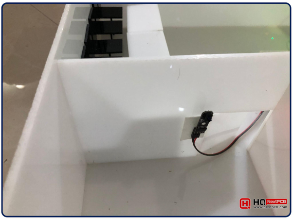
- Counter IR Sensor: To detect unauthorized entry in the Counter Section.
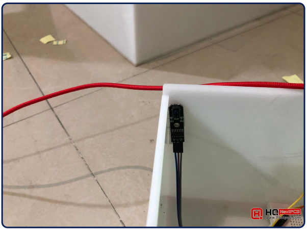
IR Sensors are placed at the doors of these sections to constantly monitor the people’s flow.
Keypad for Vault PinCode
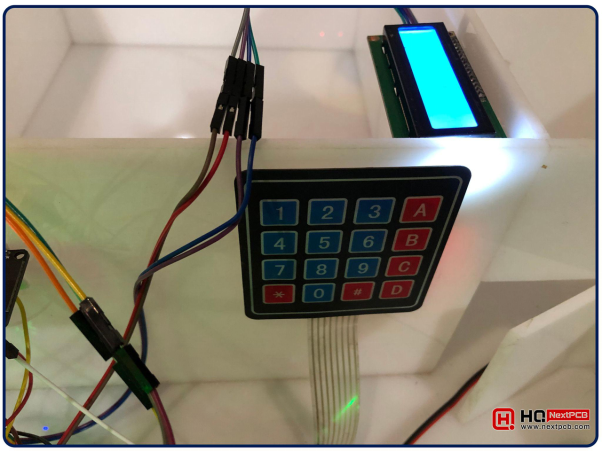
The Bank Vault is the most secure section of the bank as it stores money, so only bank officials should be allowed in this section. For that purpose, we have placed a Keypad at the door with an authorized PinCode. The vault will be unlocked only if the correct PinCode is entered using the Keypad. If someone enters the wrong PinCode, the Vault will get locked and authorities will be informed via WebServer.
ESP32 WebServer
The brain of this project is ESP32 Microcontroller board, shown in the below figure:
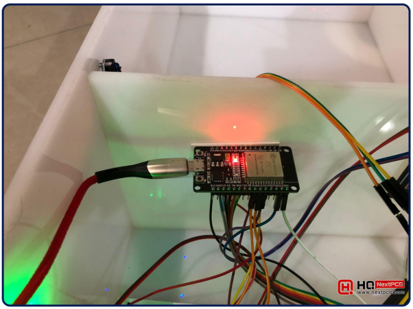
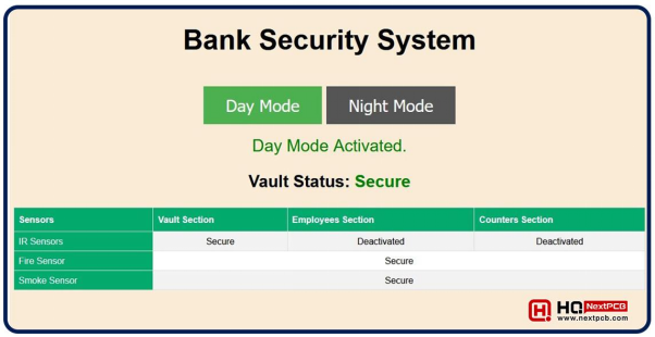
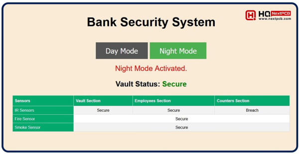
We have created a WebServer in the ESP32 Microcontroller Board. This WebServer will send the sensors’ data and notifications/alarms to the control room. The WebServer interface is shown in the below figure:
Components Used
We have used the below components for designing this Smart Bank Security System using ESP32:
- ESP32 Microcontroller Board.
- I2C LCD 16x2
- Keypad 4x4
- Fire Sensor
- Smoke Sensor
- IR Sensor x 3
- Jumper Wires
- Breadboard
I hope now you have understood what we are trying to design and the components required to design it. So, let’s interface these components together:
Circuit Diagram
The brain of our project is the ESP32 Microcontroller board. So, we need to interface all of our modules with the ESP32 board. Let’s first have a look at their circuit diagrams one by one, after that will design the ESP32 programming code.
ESP32 with I2C LCD
The Circuit Diagram of interfacing ESP32 with I2C LCD is shown in the below figure:
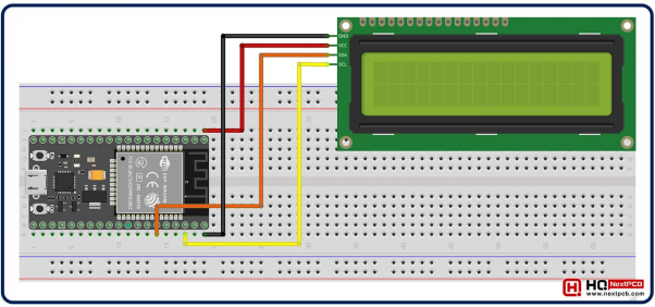
As you can see in the above figure, we have connected the SDA and SCL pins of LCD with Pins 21 and 22 of ESP32 respectively. The below table shows the ESP32 LCD Pinout:

|
ESP32 |
I2C LCD 16x2 |
|
GND |
GND |
|
VIN |
Vcc |
|
Pin 21 |
SDA |
|
Pin 22 |
SCL |
ESP32 with Keypad 4x4
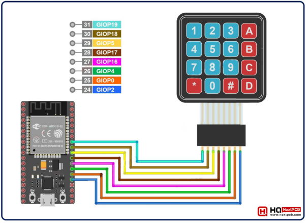
We have used a 4x4 matrix Keypad for Vault PinCode authentication. 4x4 Keypad has 8 pins in total and we can connect these pins with any 8 I/O Pins of ESP32, as shown in the below figure:
ESP32 with Sensors
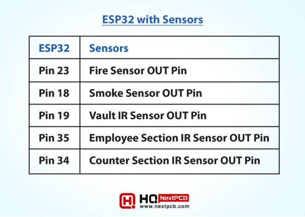
Lastly, we need to interface the sensors with ESP32 board. The Vcc and GND pins of all these sensors needs to be connected with the Vin and GND of the ESP32 board. The connection of Signal Pins of these sensors is shown in the below table:
|
ESP32 |
Sensors |
|
Pin 23 |
Fire Sensor OUT Pin |
|
Pin 18 |
Smoke Sensor OUT Pin |
|
Pin 19 |
Vault IR Sensor OUT Pin |
|
Pin 35 |
Employee Section IR Sensor OUT Pin |
|
Pin 34 |
Counter Section IR Sensor OUT Pin |
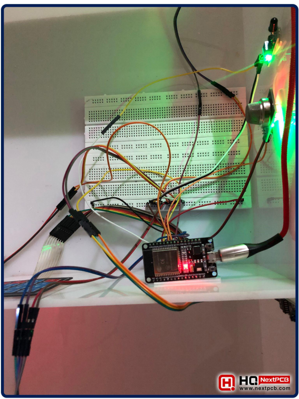
These connections on the real hardware are shown in the below figure:
We are done with all of our connections, now let’s design the Programming Code to implement our logics:
ESP32 Programming Code
We have used Arduino IDE to write the programming code for ESP32. Here’s the complete code:
|
|
Now, let’s understand the code step by step:
Understanding ESP32 Code
First of all, we need to add the required libraries:

- WiFi.h Library is used to create the WebServer in ESP32.
- LiquidCrystal_I2C.h Library is used to control the I2C LCD.
- Keypad.h Library is used to control the Keypad 4x4.
Keypad Initialization
Next, we need to initialize our variables, so let’s first map the Keypad pins and create its object, as shown in the below figure:

LCD Initialization
Next, we need to create the LCD object, as shown in the below figure:

Change Network Credentials
The below code is creating the WebServer object. Here we need to provide the network credentials:

In the above code, we need to change the SSID and Password.
- SSID: Change it to your network’s SSID.
- Password: Change it to your network’s Password.
Variables Initialization
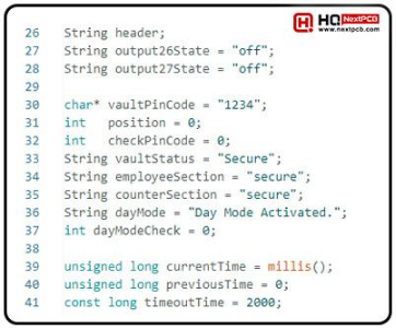
In the below code, I have initialized the variables with default values, we will use them later in the code:
Sensors Initialization
In the below code, I have assigned the sensors to respective ESP32 pins:
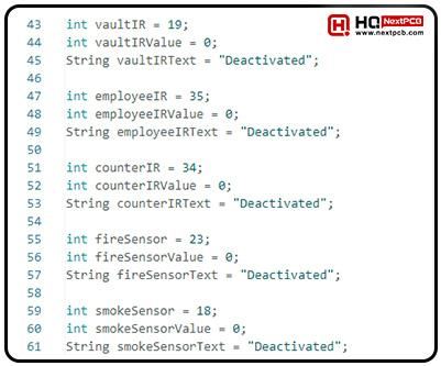
The variables with “Text” at the end are used to display the sensors’ states on the WebServer.
Setup() Function
The below code shows the Setup() Function, here we need to add the initial settings for our modules:
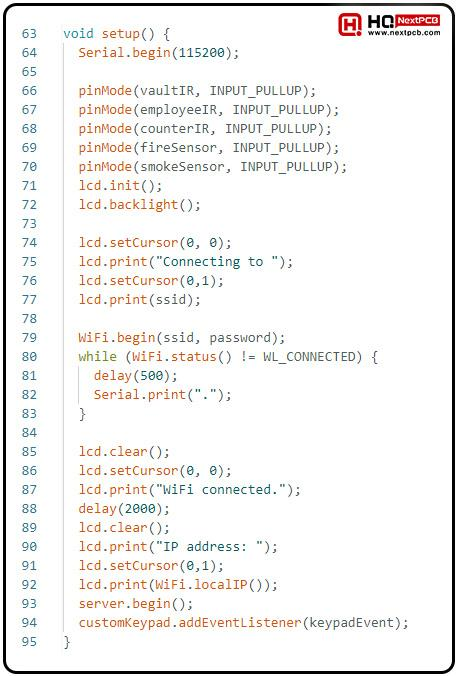
Let’s quickly go through the Setup() code:
- First of all, we begin the Serial Port at baud rate 115200. It’s used to debug the code in the Serial Monitor.
- Next, we changed the pinMode of sensor pins to INPUT_PULLUP. Pullup is preferred as it ignores the noise.
- After that, we initialized the LCD, turned on its backlight and printed the first message “Connecting to {ssid}”.
- Next, we used the while loop to wait for the ESP32 to get connected with our Network. Once the WiFi get connected, the compiler will get out of the while() loop.
- Next, we printed the ESP32 IP Address on the LCD screen and begin the WeServer.
- Finally, we added the EventListener to the keypad, it will detect the buttons pressed on the keypad. We have assigned keypadEvent() Function to this Event Listener. Let’s have a look at this function:
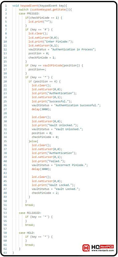
keypadEvent() Function
The keypadEvent() Function will detect the keys pressed on the keypad, we have added this function in the AddEventListener, so its interrupt based.
Here, we have first detected the “#” key, once this key is pressed, the code will wait for the user to enter the 4 Pin Authentication Code. When the “*” key is pressed, the code will compare the PinCode with the Admin PinCode and will display the result on the LCD.
The KeypadEvent() Function is shown in the below figure:
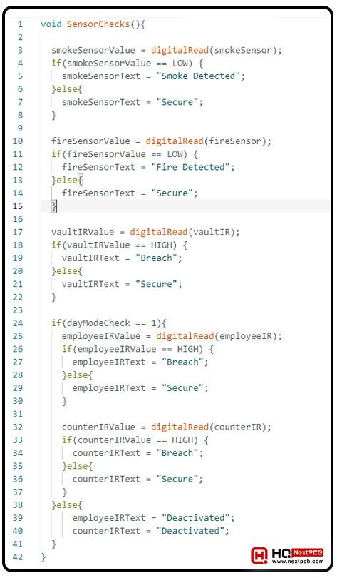
SensorChecks() Function
In the SensorChecks() Function, we are checking the state of each sensor and updating the server strings i.e. if smoke sensor is LOW, we are printing “Smoke Detected” on the WebServer and if its HIGH, we are printing “Secure”. Moreover, if the dayModeCheck variable is 1, it means the system is operating in the “Night Mode”. So, Employee & Counter IR Sensors will only work when dayModeCheck == 1(Night Mode).
Loop() Function
In th Loop() Function, we are first detecting the pressed keypad button and after that calling the SensorChecks() Function.

Next, we are checking the webServer, so if someone entered the ESP32 IP address in the web browser, the WiFiClient will get HIGH and the ESP32 will send a webPage(front-end) to the user, that will be displayed in the browser. Here’s he head section of the webPage:
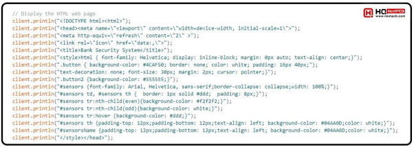
The body section of the webPage is shown in the below figure:
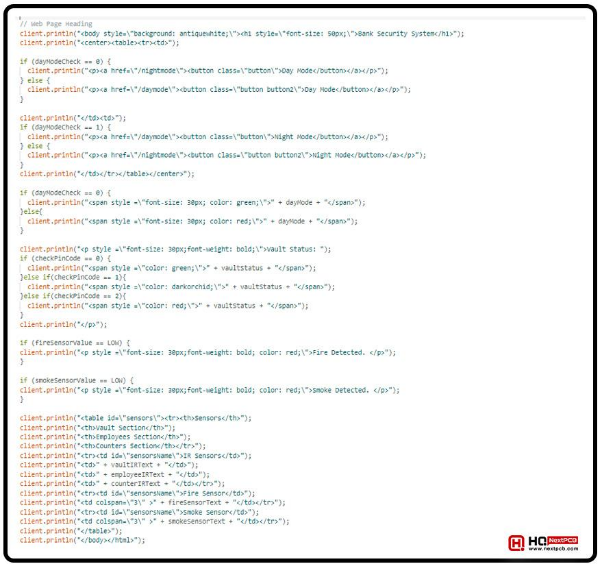
As you can see in the above code, we have placed several checks i.e. if the dayCheck is LOW, display the Green Button for Day Mode and grey button for the Night Mode. Moreover, we are displaying the Vault Statues i.e. Vault Locked, Vault Unlocked or Authentication in Process. Lastly, we displayed the sensor’s values in a tabular Form.
Now let’s upload the code in the ESP32 Microcontrolelr Board and check the results:
Smart Bank Security System - Results
After uploading the code in the ESP32 board, if everything goes fine, you will get the below results:
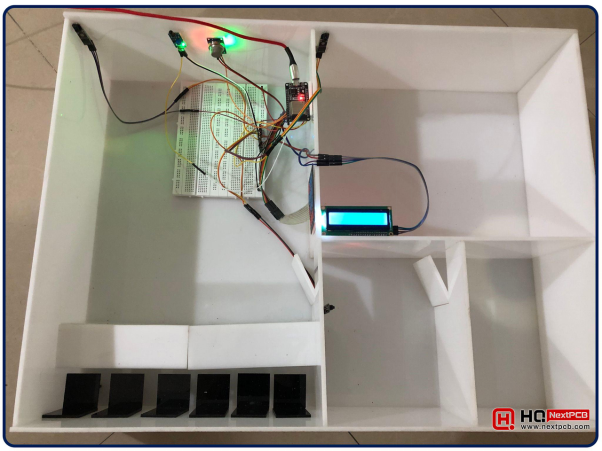
Let’s focus on the LCD screen, you will get the below display on the LCD screen:
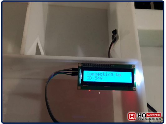
Meanwhile, the ESP32 is trying to connect to the WiFi network, provided in the programming code. Once it gets connected to the network, the below message will be displayed on the LCD:
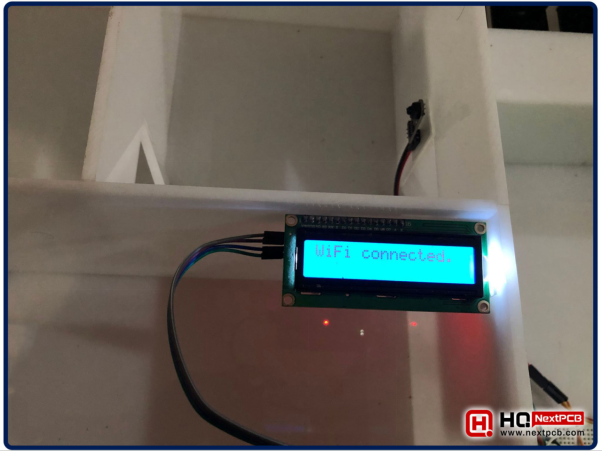
Finally, it will display the ESP32 IP Address on the LCD screen:
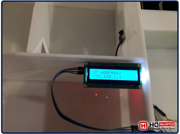
Now, enter this IP Address in the web browser and the below webPage will open up:
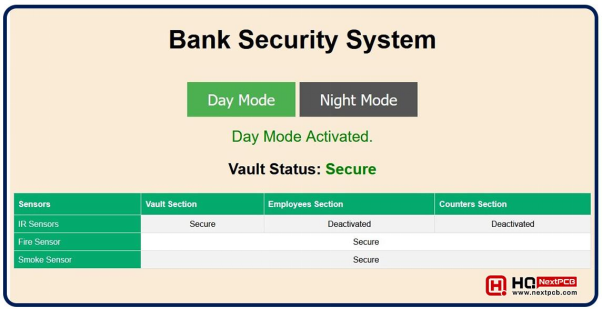
As you can see in the above figure, the IR Sensors of Employee Section & Client Section are Deactivated because we are operating in the Day Mode. So, let’s click on the Night Mode Button and we will get the below results:
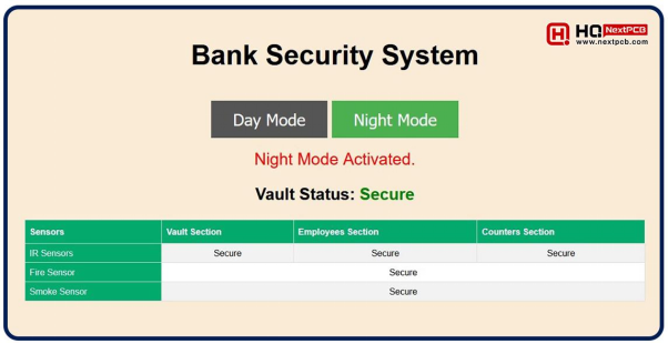
As you can see in the above figure, the Night Mode is Activated and now the system is monitoring all the sensors. Currently, the Vault status is displayed “Secure”. Now ,let’s enter the PinCode to open the Vault. So, press the “#” key on the keypad and the Vault Status will be displayed as follow:
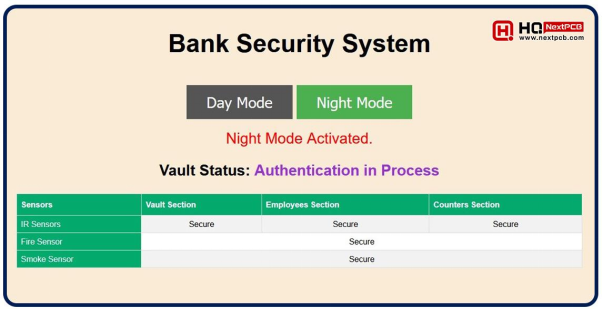
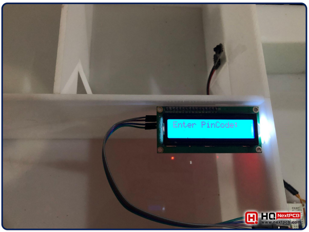
The LCD display will also ask to Enter PinCode, as shown below:
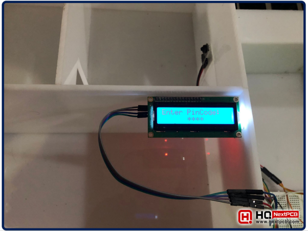
The Admin PinCode added in the programming code is “1234”, so let’s enter this PinCode:
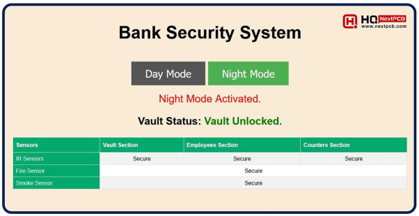
If the user entered the corred PinCode, the Vault will get Unlocked and the below status will be updated on the WebServer:
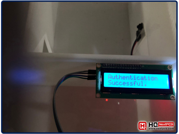
The LCD screen will also display the Authentication Succesful message, as shown in the below figure:
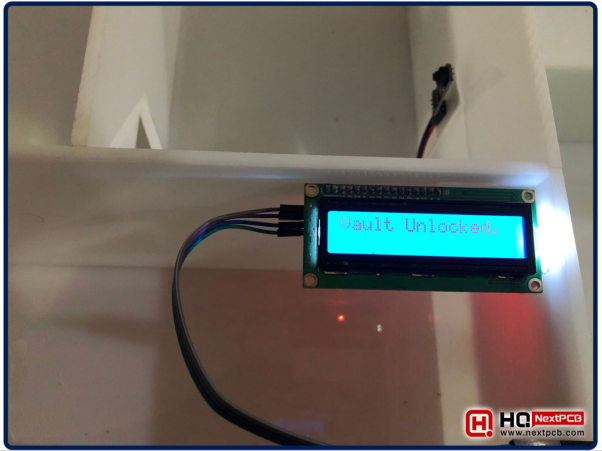
After that, will display the Vault Unlocked message, as shown in the below figure:
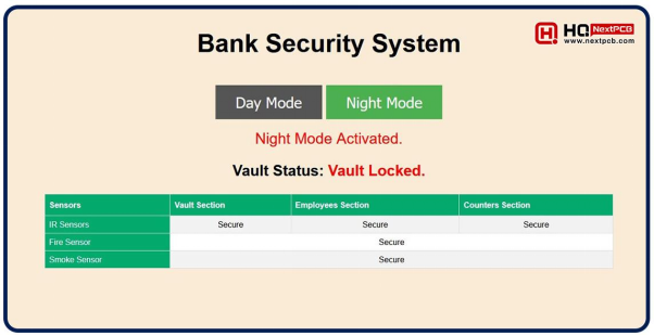
If the user entered the wrong PinCode, the Vault will get Locked and the below status will be updated on the WebServer:
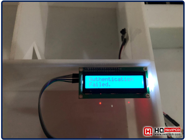
LCD screen will also print the Authentification Failed message:
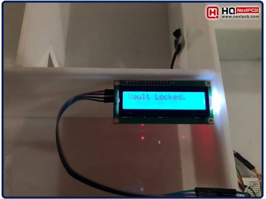
Vault Locked message will also be displayed on the LCD screen:
Now let’s test the sensors, I have placed a burning matchstick infront of the Fire sensor and the below result is updated on the WebServer:
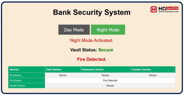
Next, let’s test the Smoke Sensor, so I have placed a lighten up cigarette infront of the Smoke Sensor.(We are just using cigarette for testing. Warning: Smoking is injurious to health.)
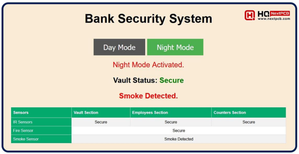
Next, we need to test the IR Sensors, so place a hand infront of the Vault IR Sensor and the status of Vault IR Sensor will be changed to “Breach”.
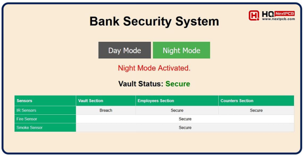
If the IR Sensor of Employee Section will detect any hurdle, its status will be updated as follows:
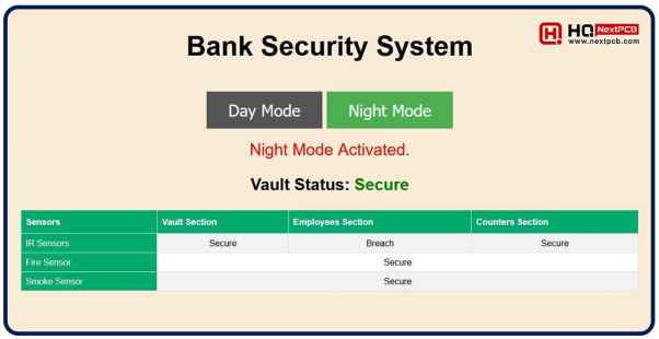
Lastly, palace something infront of the Counter Section IR Sensor, and its status will be updated as follows:
So, that was all for today. I hope you have enjoyed reading this tutorial and will be able to design it on your own. If you have any quarries, regarding this project, please ask in the comments. Thanks for reading. Have a good day.

Comment