Hi readers! I hope you are having a good day. Today, we will design a Proteus Simulation of Traffic Signal Control with a 555 Timer. As we all know, traffic signals consist of 3 LEDs(Red, Amber & Green), which operate in a specific sequence and are used to control the traffic flow and help pedestrians cross the roads. The sequence of Traffic Signal LEDs is shown in the below figure:
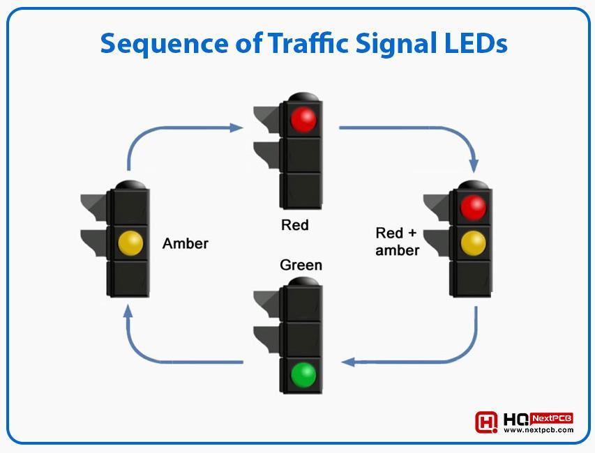
Figure 1: Sequence of Traffic Signal LEDs
Let’s translate the above figure in simple words:
- The RED LED turns ON for some duration (normally 1-5min, depending on the traffic density), while the other two LEDs(Yellow & Green) remain OFF.
- When the Red LED is about to turn OFF, the YELLOW LED turns ON for a moment(normally 5-30sec) and after that, both Red & Yellow LEDs turn OFF.
- When the Yellow & Red LEDs turn OFF, the GREEN LED turns ON for almost the same duration as the Red LED.(& the cycle continues)
- When the Green LED gets OFF, the YELLOW LED turns ON for a moment (& the cycle continues).
Project Overview/Working
As I said earlier, today, we will design a Proteus Simulation of Traffic Light Control. In order to control the ON/OFF sequence of these LEDs, we will use a timing IC 555 Timer and a decade counter CD4017. The project working revolves around the combined action of 555 Timer and CD4017 ICs. The final Proteus Simulation of this project is shown in the below figure:
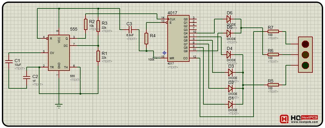
Figure 2: ProteusSimulation of Traffic Light Control
Now, let’s have a look at why we need to use this timing IC 555 Timer to design this project:
Why 555 Timer?
It's quite clear that, in order to design this project, we only need to devise a sequence for these LEDs to turn ON and OFF. We need to place a specific timer delay between the state change of these LEDs. In such specific time-based projects, the best approach is to use the most commonly used timing IC named 555 Timer. The 555 timer generates the pulses to control the signal lights at a regular interval.
So, before going forward, let’s first have a look at what is 555 Timer and how it operates:
Components Free Worldwide Shipping
What is 555 Timer?
555 Timer is a versatile timing IC that generates various types of electronic pulses i.e. normal, oscillating, variable frequency etc. 555 Timer is used in different domains of electronic circuits i.e. digital signal processing, multiplexing circuits, timer/counter circuits etc. The internal schematics of 555 Timer is shown in the below figure:
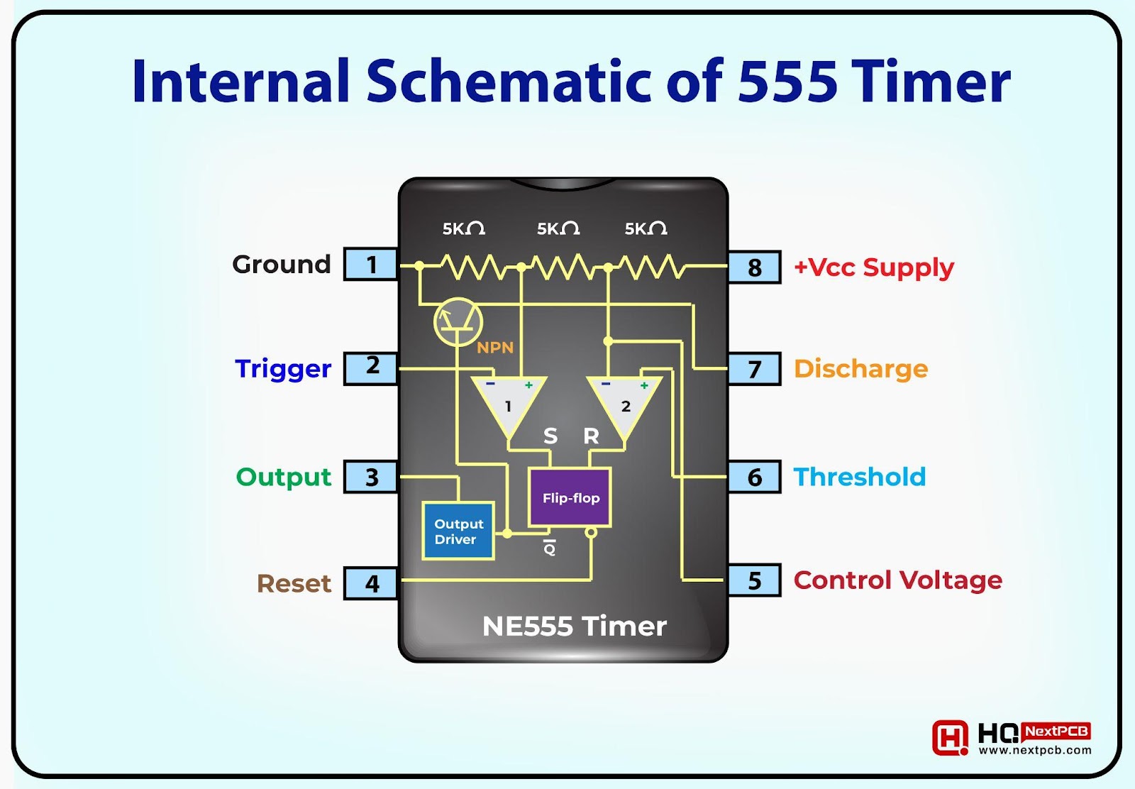
Figure 3: Internal Schematic of 555 Timer
As you can see in the above figure, the 555 Timer consists of two comparators and a flip-flop. We will create a simple circuit by using passive components(i.e. resistors & capacitors) at the comparators' inputs, threshold and Control Voltage pins. As a result, the 555 Timer will generate a sequence of electronic pulses at the Output Pin. The values of passive components will decide the duration of electronic pulses.
In this project, 555 Timer is configured as an astable multivibrator, which means it generates a continuous flow of rectangular electronic pulses with a specific frequency. In simple words, 555 Timer acts as an electronic oscillator and generates sequential signals. Moreover, 555 Timer produces the signals without any external trigger as traffic signal is an automated process.
Now let’s have a look at the role of decade counter CD4017:
What is CD4017?
CD4017 is a decade counter, which means it can count from 0 to 9. It has a total of 10 output pins from Q0-Q9 and a single clock pin(CLK). When the Clock pin gets HIGH, the counter output pins increment by 1. When the counter gets from 0 to 9, it resets itself and starts counting again. The pinout of CD4017 is shown in the below figure:

Figure 4: Pinout of CD4017
The output pulses generated by the 555 Timer are fed into the clock signal(CLK) of decade counter CD4017 and the Traffic Signal LEDs are placed at the output of the CD4017. Depending on the pulse duration, the output of the CD4017 gets incremented and turns ON/OFF the LEDs.
Passive Components
Along with the ICs, these passive components are used in this project:
- Resistor: Limits the current flow through the circuit, and when used with the 555 timer, it helps in the charging and discharging process of the capacitor. Another function is to work on the voltage division across the circuit.
- Capacitor: It continuously charges and discharges and thus affects the duty cycle and frequency of the output waveform of the 555 timer in astable mode. It is used to generate a specific waveform shape.
- Diodes: Allow the current to pass in one direction only and are used to increase the delay between LEDs.
Components Used
Here’s the complete list of components used to design the Proteus simulation of traffic light control:
- 555 timer IC
- 4017 IC
- Capacitors x 3
- Resistors x 7
- Diodes x 6
- Traffic lights
Now let’s start designing the Proteus Simulation of Traffic Signal Control:
Proteus Simulation of Traffic Signal Control
- Create a new project in Proteus ISIS.
- Click on the pick library button and get the below components in your workspace:
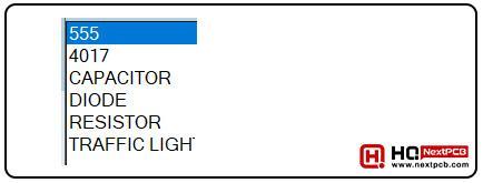
Figure 5: Components used in Proteus Simulation
- Design the 555 Timer circuit by connecting the passive components with values, as shown in the figure below:

Figure 6: 555 Timer Basic Circuit
- Set the circuit of the 4017 IC and passive components according to the given circuit:
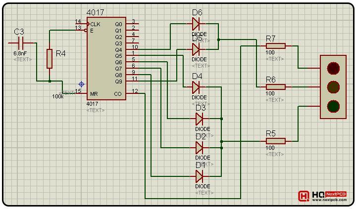
Figure 7: CD4017 Basic Circuit
- The values of capacitors & resistors used in this simulation are given in the below table:
|
|
|
|
|
|
|
|
|
|
|
|
|
|
|
|
|
|
|
|
|
|
|
|
|
|
|
|
|
|
Table 1: Capacitors & Resistors Values
- So, now combine both the circuits to get the resultant output:
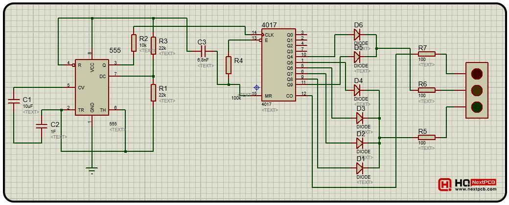
Figure 8: Complete Proteus Simulation of Traffic Light Control
- Click on the play button to start the simulation, and if everything goes well, you will get the results as shown in the next section.
Traffic Light Control - Results
After the successful connection of each component, the traffic signals vary according to the values of the capacitors we’ve set. Initially, the red light flashes for three seconds, signaling a stop.

Figure 9: Red LED ON State
Following the red light phase, the yellow light illuminates briefly before transitioning to the green light, as shown in the below figure:
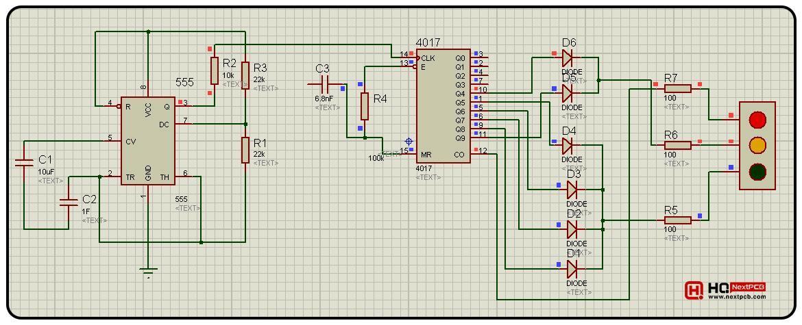
Figure 10: Red and Amber LEDs ON State
Finally, the Green LED will turn ON while the Red and Yellow LED will turn OFF, as shown below:

Figure 11: Green LED ON State
After a particular time, a yellow light reappears for a set duration, followed by the return of the red light. This cyclic process effectively simulates automated traffic signals.
How to Change the LEDs ON/OFF Duration?
The ON/OFF duration of traffic signal LEDs mainly depends on the below two factors:
- Traffic Density
- No. of Traffic Lanes
So, for a practical approach, your circuit must have the flexibility to adjust the LEDs ON/OFF duration. In our circuit, we can change the LEDs duration by changing the values of C1 and C2 capacitors, attached at Pin # 2 and 5 of the 555 Timer. I have encircled these capacitors in the below figure. So, play with these capacitors and check the impact on the LEDs On/OFF states.
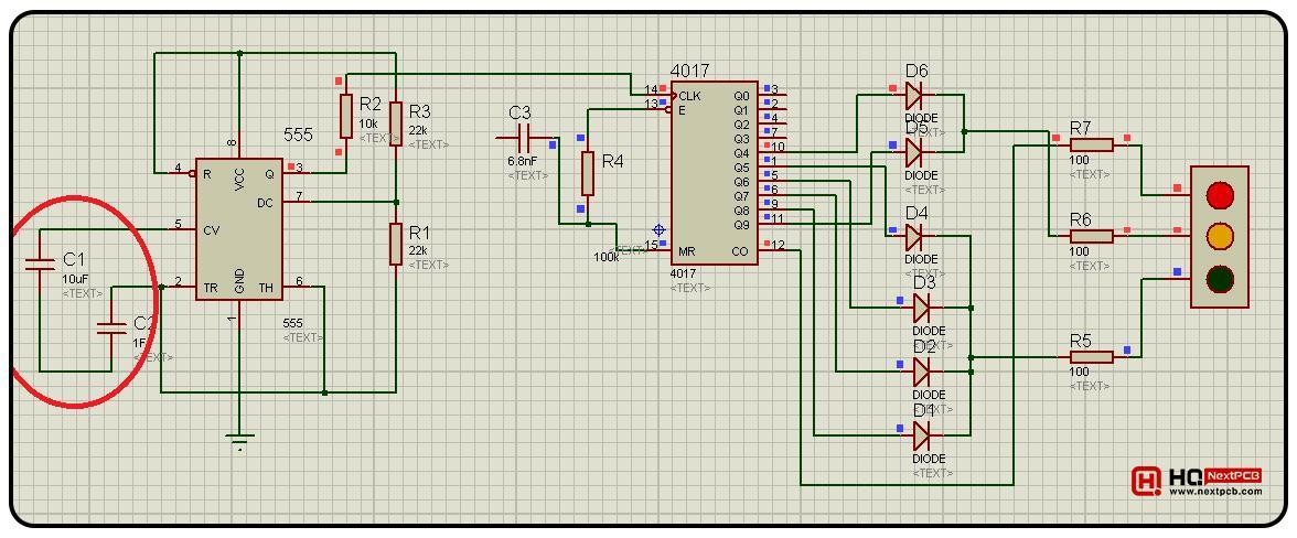
Figure 12: Capacitors encircled to change the LED Duration
So, that was all for today. I hope you understand the complete working of this project and now can easily design it on your own. Still, if you are stuck or want to know more about the project, you can ask in the comment section. Have a good day.
Comment