Introduction
PWM or Pulse Width Modulation is a quite famous and uncomplicated scheme to control motor speed. Here, we will explain the concept of PWM concerning its application on the 555-timer integrated circuit that can be applied to the control of a particular speed of a DC motor.
The 555 timer is one of the most versatile integrated circuit basic timing devices which is very useful in circuit designing. All that is needed is incorporated inside this package to enable the production of accurate time-delayed oscillations or simply by using external resistors and capacitors. In addition to price and availability, the 555 timer is a user-friendly component used for several functionalities even in the present time some of which involve PWM motor speed control.
Thus, let me expand on the principles of PWM and explore how one can implement it with the help of a 555 timer when controlling the pace of the DC motor.
What is PWM?
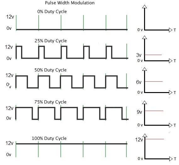
Pulse Width Modulation or PWM as it is abbreviated is defined as a technology employed in giving a pulse train a specific code. PWM on the other hand varies the width or duration of the pulse while the frequency or the pulse per second remains constant. This change in the length of the pulse over time works as the modulation.
The basic idea behind PWM is to provide an effective voltage to a load by switching between the ON and OFF states of the power supply. A longer ON time corresponds to a higher voltage and vice versa. By varying the ON/OFF time ratio or duty cycle, the effective voltage supplied to the load can be controlled even though the power supply voltage remains constant.
For example, consider a 12V power supply feeding a motor through a transistor switch that is closed for 1 ms and opened for 1 ms repeatedly. The effective voltage supplied to the engine will be half of 12V i.e. 6V. Now if the switch is closed for 2ms and opened for 1ms, the duty cycle increases, and the effective voltage will be higher at 8V.
So in summary, PWM modulates the width of pulses to produce variations in the average value of the supplied voltage even though the amplitude remains constant. This principle allows the control of motor speed, light intensity, sound volume, etc using low-power electronic switches.
PWM and Motor Speed Control
DC motors are generally controlled by varying the voltage supplied to them. Higher voltages result in faster motor speeds. However, continuously varying the supply voltage is not practical and efficient.
Using PWM for motor speed control provides an elegant solution. The transistors acting as electronic switches are turned ON and OFF rapidly. Adjusting the duty cycle of these pulses is more effective in modulating the average voltage across the motor while the supply voltage remains unchanged.
At low-duty cycles, the motor receives power for only a small fraction of the total time. This results in a lower average voltage and slower motor speed. Gradually increasing the duty cycle by keeping the pulses wider open for more time increases the average voltage and motor speed.
So in summary, PWM gives us digital control over analog voltage/speed by changing the duty cycle. This allows efficient electronic control of motor speed from a constant voltage power supply.
555 Timer Operation
Till now we have seen a simple frequency-to-voltage converter using a 555 timer but here we are going to see how the same 555 timer IC can be used to generate PWM signals for speed control. 555 is an integrated circuit that is used as a timer, it generates accurate time pulses.
Internally, the 555 timer contains two stable voltage levels - a high VCC and a low ground along with a central comparator. An external RC charging/discharging network connected between Trigger and Threshold pins is used to determine the time of output pulses.
In astable mode configuration, the 555 produces a continuous train of square waves at its output pin with a frequency determined by the external RC components. During one cycle, the capacitor charges through the resistor until it reaches the trigger voltage.
The output then switches to its opposite state discharging the capacitor through the threshold pin until it reaches the reset voltage. Then the cycle repeats thus producing a square wave.
By changing the RC values, we can vary the ON and OFF times of the 555 output pulses. The duty cycle or ratio of ON to total time is determined by the ratio of R and C values in the timing network.
So the 555 IC in an astable configuration functions perfectly as a PWM signal generator with an adjustable duty cycle by simply tweaking the external resistor and capacitor values.
555 PWM Motor Control Circuit
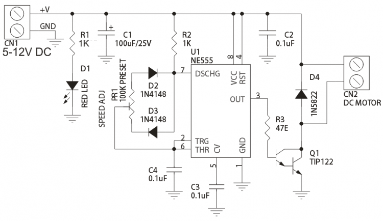
Now let's look at the complete circuit to control a motor speed using 555 PWM:
- Connect the 555 timer in astable mode configuration with a resistor and capacitor forming the timing/charge-discharge network between Trigger and Threshold pins.
- Provide a power supply like a 9V battery to VCC and ground pins to power the 555 timer IC.
- Fixed IC 555 output pin to base of NPN transistor with a bias resistor.
- The first step involves grounding the emitter of the transistor and joining the collector end to one of the motor terminals.
- Solder the other terminal of the motor to the positive terminal of the voltage supply pathway.
- . So now the transistor acts as an electronic switch for the motor.
- Adjustment of the RC timing network controls the output PWM frequency and duty cycle of 555.
- Varying duty cycle modulates the average voltage seen by the motor which regulates its speed.
So as the PWM output from 555 switches the transistor ON and OFF rapidly, the motor receives a variable average voltage depending on the duty cycle. This allows the motor speed to be smoothly controlled electronically using just a 555 timer IC and minimal external parts.
Enhancing the Design
Expanded Speed Range Using Gearing
- Mechanical gearing can help access lower motor speeds that may not be achievable through PWM alone.
- For example, a 50:1 gear reduction would multiply the motor shaft RPM by 50x, allowing finer low-speed control.
- Planetary or worm gear sets provide high reduction ratios in a compact package suited for robotics or CNC machines.
Closed-Loop Control for Enhanced Precision
- An encoder on the motor provides feedback to a microcontroller running a control algorithm.
- PID controllers can precisely match and maintain the commanded speed by adjusting the PWM duty cycle based on error.
- This compensates for variations in load/supply better than open-loop control.
Digitally Programmable PWM Frequency
- A microcontroller or dedicated PWM IC allows software-defined PWM frequency instead of fixed timing components.
- Higher frequencies reduce audible motor noise and torque ripple. Lower frequencies improve efficiency at low speeds.
Overvoltage Protection
- A crowbar circuit uses a thyristor or SCR to short the supply during overvoltage, protecting components.
- Prevents damage from back-EMF, load dump, or improper wiring that could otherwise cause transistor avalanche.
Heat Sinking and Ventilation
- Mounting MOSFETs/transistors to an aluminum plate aids heat dissipation during prolonged high-load operation.
- For enclosed spaces, small fan cooling prevents thermal throttling or components exceeding their maximum ratings.
Those are some additional tweaks that can enhance the robustness and precision of a PWM motor speed control scheme using a 555 timer or other basic controllers. Let me know if any part needs more explanation!
Testing and Demonstration
Let's now demonstrate this PWM motor speed control circuit in action:
- First, assemble the circuit on a breadboard as shown in the diagram with appropriate component values.
- Use a 9V battery for power supply, general purpose NPN transistor, small motor, and timing components within the 555 operating range.
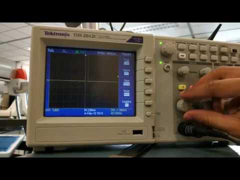
- Adjust the RC values slightly and observe the output pulse train on the oscilloscope if available.
- Otherwise, connect the 555 output to the LED to see the blinking indicating PWM generation.
- Now connect the motor and observe it running at a steady but medium speed initially due to a 50% duty cycle.
- Gradually increase the timing capacitor value to increase the duty cycle in steps. Note the motor is accelerating smoothly.
- Similarly, reduce the capacitor to decrease the duty cycle and observe the motor slowing down controllably.
- The motor speed can be varied smoothly from zero to maximum rated rpm by adjusting the single timing capacitor value.
- This successful demonstration exemplifies effective digital speed control of the motor using a simple PWM technique.
Precision Speed Control
While the basic 555 PWM circuit allows smooth variations in motor speed, more precision may be required for specific applications. Here are some ways to improve the resolution and accuracy of speed control:
- Use a multiturn trimpot/potentiometer instead of a fixed resistor for the timing RC network. This gives continuously adjustable timing capacitor value for finer speed adjustments.
- Add a digital potentiometer which can be precisely controlled using a microcontroller. Popular ICs like MCP41010 allow 10-bit resolution for timing components.
- Replace the 555 with a dedicated PWM controller IC like TLC5947. It features a 12-bit internal DAC and a programmable frequency/duty cycle for higher precision speed settings.
- Connect encoder feedback on the motor shaft. Use the readings in a closed loop control using a microcontroller to minimize speed fluctuations and precisely match command values.
Protecting Transistor and Motor
Proper circuit protection measures need to be incorporated to prevent component damage from overcurrent:
- Use a power transistor rated for the motor's stall/starting current. Common types are TIP120, 2N3055, IRF530, etc. matching transistor and motor specs.
- Connect a flyback/freewheeling diode across the motor terminals to handle back-EMF safely during PWM off-cycles.
- Place a fuse in series on the power supply line for overcurrent safety cutoff. Use a 2-3A fast blow fuse for a small motor circuit.
- Add a thermal shutdown feature using a thermal switch/PTC resistor connected to the transistor collector. It will cut power automatically if the temperature exceeds safe limits preventing overheating.
Speed Range Adjustment
Just varying the PWM duty cycle can allow a limited usable speed range. Here are ways to widen the operational span:
- Combine PWM control with a variable voltage regulator to get both fine and coarse speed adjustment capability over a broader range.
- Implement separate high and low side power MOSFET switching for H-bridge motor control topology. It enables forward/reverse operation and efficient braking control.
- Leverage user-selectable voltage supplies like 3-12V adapters to suit motor/load characteristics and application requirements.
- Gear down mechanical transmission to reduce maximum no-load speed if required to access lower operating RPM range via PWM.
Oscilloscope Measurements
Validating circuit operation and optimizing parameters requires inspecting waveforms:
- Connect the oscilloscope probe at 555 output to examine PWM signal quality- observe clean square pulses at a set frequency.
- Probe across motor terminals, duty cycle changes should translate to average voltage modulation cleanly.
- Check for electromagnetic noise coupling into supply/signal lines which may cause jitter- add decoupling caps, and isolate wiring as needed.
- In closed-loop systems, scrutinize PI controller output and encoder feedback signals for proper tracking and stability.
Alternative Controller Options
While the 555 timer remains a simple low-cost option, other IC families provide added features:
- Tiny/ATtiny microcontrollers - Their internal or external ADC, PWM, and control peripherals allow more sophisticated speed regulation algorithms.
- Motor driver ICs – L293, and L298 integrate H-bridge for easier bidirectional control of higher-power motors compared to discrete drivers.
- Brushless DC motor controllers – DRV8301, EasyDriver, etc. simplify driving brushless motors with integrated PWM, commutation, and current sensing.
- Arduino platform – Allows rapid prototyping with abundant examples available for PWM-based motor control using atmega328/2560 and motor driver shields.
Digital Potentiometer for Precision Timing
A digital potentiometer allows the timing resistor or capacitor values to be precisely adjusted using microcontroller I/O lines. This provides software-defined timing resolution.
The MCP4451 is a popular SPI-interfaced digital potentiometer suitable for this application. It has a Wiper voltage range of 0-Vcc with independent 4096-step increments on each of its 4 channels.
By connecting one of these channels as the timing resistor in the 555 astable multivibrator, the PWM duty cycle can now be programmed in 4096 discrete steps instead of using a fixed resistor.
This gives much finer control over motor speed compared to analog potentiometers. The microcontroller simply needs to output the desired wiper setting as a 12-bit value on the SPI bus to adjust timing.
Programmable PWM Using Microcontrollers
Replacing the 555 timer with a small microcontroller like ATtiny85 allows software-defined PWM generation. Its integrated 8-bit timer peripherals support frequencies from 31Hz to 8MHz.
The OCRnx registers to determine the pulse width as a percentage of the entire period set using ICRnx. Programming these registers in a loop achieves glitch-free analog-equivalent PWM without external components.
Additionally, the resolution can now match the processor's clock for much finer levels of speed modulation compared to timers like 555 with limited RC clocking.
Sensor Feedback and Closed-Loop Control
A rotary encoder disk attached to the motor shaft provides rotational position and speed feedback. As it rotates, the encoder outputs digital pulses on two channels that are 90° out of phase.
By counting pulses on each channel within a known time interval, the microcontroller can accurately determine the motor's RPM. It then compares the measured speed to the target value and accordingly makes adjustments to the PWM duty cycle.
Proportional-integral-derivative (PID) control algorithms are commonly used for closed-loop functions. The PID parameters can be tuned experimentally for an optimal response without steady-state error or overshoot at different load conditions.
This feedback-based approach provides precise speed regulation and compensation for variations better than an open-loop PWM scheme alone.
Programmable H-Bridge Motor Driver
Dedicated motor driver ICs with an integrated H-bridge simplify driving bipolar DC motors with greater current capability than small transistors.
The DRV8838 is an example of a bipolar stepper motor driver that can also control brushed DC motors. It accepts standard PWM inputs and internally commutates the H-bridge for bidirectional rotation.

An onboard current sense comparator protects the motor from overcurrent. Its maximum output current is rated at 1A continuous which is adequate for medium power applications. The enable/direction pins are controlled by microcontroller GPIOs.
This removes the complexity of designing external discrete H-bridge circuits using power MOSFETs or Darlington transistors and allows compact motor interfacing.
Thermal Management and Protection Circuits
Proper heat dissipation becomes critical at high-duty cycles to prevent thermal throttling or damage. Mounting power transistors/ICs to an aluminum heatsink transfers heat efficiently to the environment.
Thermal switches/PTC resettable fuses placed between components and ground cut power when their preset temperature is exceeded, acting as simple over-temperature protection without microcontroller intervention.
Crowbar circuits protect from transient overvoltage events by clamping supply voltage below component breakdown ratings using devices like thyristors, protecting expensively while restoring function automatically after the fault clears.
Adding these thermal designs and overvoltage/current monitors results in a safely rugged motor speed controller optimized for continuous heavy-load applications.
I hope these extra details provide useful insights into designing and implementing more robust and advanced digital PWM motor speed control systems beyond a basic 555 timer approach. Let me know if any part needs more explanation.
Applications
The PWM-based motor speed control using 555 timer has numerous practical applications due to its simplicity and versatility:
- Model vehicles/robotics - Control the speed of DC brushed motors in RC cars, boats, drones, etc.
- 3D printers - Vary the rate of filament feed and stepper motor movement for multi-material printing.
- CNC machines - Regulate spindle and servo motor speeds digitally in CNC routers and mills.
- Home appliances - Adjust fan speeds, and wash/dry cycles using PWM-controlled brushless motors.
- Industrial automation - Control conveyor speeds, and pump flow rates by modulating motor voltages.
- Solar pumping - Use PWM to operate DC water pumps powered by solar panels efficiently.
- RC servos - Provide proportionate steering/flap actuation based on pulse width from the remote.
So in summary, PWM-based motor control opens up many possibilities for digital speed regulation across sectors using simple and low-cost implementations.
Conclusion
In this article, we discussed the concepts behind PWM and how it allows digital control over analog systems like motors. We then explored the internals and operation of the 555 timer IC for generating adjustable PWM pulses.
Finally, a complete PWM motor speed control circuit was designed using a 555 timer and its working was demonstrated. This method provides an elegant yet practical solution for digitally regulating motor speeds from a fixed voltage supply with minimal components.
The 555 timer PWM technique discussed here has widespread applications and remains relevant even in today's era of powerful microcontrollers. I hope this article provided useful insights into applying this simple yet powerful control method. Please feel free to experiment further and share your thoughts.
Comment