A Digipot is also called a digital potentiometer often termed a high-precision digital variable resistor. They offer better control of analog signals in electronic circuits and devices by using (voltage) signals as opposed to a mechanical knob or slider encountered in a potentiometer. To be more precise, in this guide, we will briefly explain what digital potentiometers are, and the specifications of the most common ones, and then we will guide you through the process of using digital potentiometers with an Arduino microcontroller board. Soon, you will gain enough knowledge on how to use the digipots within the electronic projects you are undertaking and how they work.
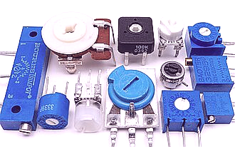
Examples of some classical trimmers/potentiometers
What is a Digital Potentiometer?
A digital potentiometer or digipot is defined as an electronically controlled potentiometer that works like a linear motor. It can likewise be used to control voltage which is just like a regular potentiometer used in circuits that require adjustments to the amount of resistance. However, rather than being adjusted using a shaft or a slider, it is controlled electrically in terms of the voltage.
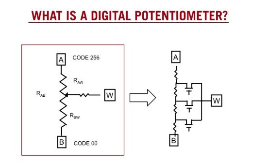
The primary feature of a digipot is in the digital control interface; where the resistor setting of the digipot is set and controlled digitally via protocols such as SPI or I2C. This digital interface is referred to as a microcontroller or other digital control circuit. This is achieved by sending a digital code value to the Digipot to adjust its resistance value at the microcontroller’s command.
For example, a typical 10kohm digital potentiometer may have a resolution of 10 bits, meaning it can set 1024 different resistance levels between 0 and 10kohm. The microcontroller would send it a 10-bit value from 0 to 1023 to set the desired resistance point. This gives far greater precision over a mechanical potentiometer which may only allow setting the resistance to the nearest percentage point.
Some other key characteristics of digipots:
- Non-volatile memory - Most digipots can remember their last setting even when power is removed, thanks to onboard non-volatile memory like EEPROM or FRAM.
- Variable resistance - Can simulate a potentiometer or rheostat by varying output resistance levels between minimum and maximum values.
- Small size - Modern digipots are much smaller than equivalent mechanical pots, making them well-suited for space-constrained applications.
- High precision - Multi-bit resolution of modern digipots provides repeatable resistance setting to a high degree of accuracy.
Reliability - Being electronically controlled, digipots have no moving parts so are more durable and reliable than mechanical pots over long-term use.
Programming flexibility - Resistance can be digitally programmed on the fly or through pre-configured settings, enabling more complex and dynamic control schemes.
In summary, digital potentiometers replace mechanical adjustment with digital programming to provide precise, repeatable, and versatile analog signal control for electronic design and prototyping applications. Let's now move on to interfacing one with an Arduino.
Driving Remote Digipots
So far we've looked at directly interfacing a digipot to an Arduino, but what if you want to control one remotely? Many digipots feature a built-in I2C or SPI bus that lets you daisy chain multiple pots together on the same communication lines. This enables "distributed control" where you can place digipots precisely where needed in a circuit rather than running individual wiring back to the main controller.
To drive a remote digipot, all that's needed is three additional wires - power, ground, and the digital communication line (I2C SCL/SDA or SPI MOSI/MISO/SCLK). The control signals can then be routed long distances so each pot only needs a local power and ground connection.
This expands your projects in useful ways. For example, you could control an array of LED strips, each with its digipot to set the brightness level. Or vary properties across zones in an interactive art piece or electronic musical instrument.
- Getting multiple digipots to work requires some unique addressing schemes depending on the protocol:
- I2C uses 7-bit addressing so up to 112 devices can share the bus. Assign each pot a unique address in the software.
- SPI uses chip select lines, so one CS per digipot. Run CS to Arduino ports and select pots individually.
- Daisy chain pots physically by wiring SCL/SDA or MOSI/MISO lines in series. Power all from a single source.
With addressing and wiring properly configured, the Arduino can now control an entire network of distributed digipots over just a couple of bus lines. This maximizes their spatial deployment flexibility.
Digipot Arrays for Simulation
Taking the multiple pot concept a step further, digipot arrays let you construct programmable resistance networks for advanced simulations and modeling. Imagine having an 8x8 grid of individually controlled pots. You could:
Emulate material properties by assigning resistances across the array representing something like a metal structure under load. Dynamically tweak values.
Develop variable diffusion models to experiment with heat transfer or chemical mixing processes over time by simulating diffusion constants across the "materials."
Physically map out circuit designs before building by using the array to represent resistor/component values and monitor node voltages. Quickly iterate schematic ideas.
The possibilities are limited only by your imagination for mapping real or abstract systems to a digitally configurable resistance matrix. Arrays open up modeling of multi-dimensional, time-varying phenomena not possible with single-component controls.
To construct an array, digipots must be organized either on a circuit board wired in a grid pattern or by using multiplexing. Multiplexing allows addressing individual pots within a larger physical group by taking advantage of how only one pot is active at a time:
Connect all pot power/ground pins
Run address/data lines to rows/columns
Address a row
Write data on column lines
Repeat for each pot
This saves precious I/O pins and space by treating the array as a virtual grid addressed in software rather than actual wiring. Proper row/column timing ensures unique access.
Once constructed, simulation becomes interactive by writing custom virtual "materials property" and "model state" functions to map array values to variables over time. Digipot arrays thus constitute highly programmable analog computing substrates.
Closed-Loop Control
So far we've seen open-loop use cases for digipots where a microcontroller simply writes predefined or calculated resistances. But digipots also enable closed-loop control system applications by reading their wiper outputs.
For instance, you could use a digipot as the control element in a PID (proportional-integral-derivative) controller to actively maintain some system variable at a setpoint:
- Configure digipot as feedback potentiometer
- Measure wiper voltage representing process variable
- Compare to setpoint
- Calculate PID output based on error
- Write new digipot resistance to drive the process
- Repeat in a loop
Applications include motor speed regulation, temperature control, light/sound levels, robot joint servos - anything that responds to changing resistance levels over time.
Reading the digipot also enables other control schemes:
- Feedback control of simulated systems in software
- Automated calibration/potentiometer curve characterization
- Closed-loop regulation and disturbance rejection
- Sensorless positioning for feedback-less stepping
With proper control algorithms, digipots add a closed-loop dimension to your projects for stabilized, autonomous behavior. You're no longer constrained to simple open-loop responses.
Advanced Communications Protocols
While I2C and SPI cover many digipot use cases, some models offer more exotic bus types unlocking new possibilities. For example, the MCP41xxx family supports programming over 1-Wire, allowing incredible flexibility:
- Parasitic power allows pots to operate off power sent through a single data line, enabling truly minimal wiring deployments anywhere in a circuit.
- Multi-drop capability lets you chain together an effectively unlimited number of 1-Wire devices on one port, like addressable RGB LED strips but with potentiometers.
- Unique 64-bit IDs permit directly selecting devices anywhere on the 1-Wire network without external addressing logic.
Other options include D2B communication which transmits analog resistance levels directly as audio tones for implementing "musical" controls. This bridges the digital-analog gap in creative new ways.
So don't limit yourself just to common protocols. Digging deeper into exotic comm standards unlocks new fields of application that push the boundaries of what's possible with programmable analog circuitry.
Interface a Digipot with Arduino
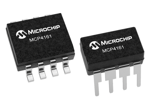
For this guide, we will use the MCP4161 digital potentiometer from Microchip Technology. It is a single-channel 10kohm potentiometer with a 10-bit resolution and I2C interface, making it well-suited for easy use with an Arduino. Here are the basic steps:
Connect the Digipot
Connect the MCP4161 to your Arduino as follows:
- VCC to 5V power rail
- GND to GND
- SCL to Analog 5 (or other I2C clock pin)
- SDA to Analog 4 (or other I2C data pin)
Install Libraries
Open the Arduino IDE and install the Wire and MCP4161 libraries. You can find them through the Library Manager.
Test Communication
Load the MCP4161_Address. in the example sketch. It tests basic I2C communication by printing the digipot address. If the address prints, I2C wiring is good.
Set Resistance
Load the MCP4161_Write. in sketch. It sets the digipot resistance to different levels and prints the value. You can now control resistance digitally.
Integrate with Project
Incorporate digipot control into your sketches as needed. Set resistance levels based on sensor readings, button presses, etc. Read value to control analog circuits.
That covers the basics of interfacing the MCP4161 digipot with Arduino. With the wiring and libraries in place, you can now programmatically control analog circuits using digital signals from the microcontroller.
Example Applications
Now that you have the fundamentals of interfacing a digipot, let's explore some example applications to put them to use:
Light Dimmer - Control an LED or lamp brightness by varying digipot resistance in its power supply circuit. Fade smoothly between levels.
Temperature Controller - Use digipot resistance to modulate heat output based on temperature sensor readings for applications like soldering stations.
Audio Mixer - Blend multiple audio signal levels electronically using digipots instead of physical knobs. Program advanced mixes.
Sensor Simulator - Emulate different sensor outputs digitally by varying simulated 'sensor resistance' with a digipot. Great for testing circuits.
Servo Speed Control - Alter RC servo speeds by adjusting digipot resistance in motor power lines. Create robotic arms with programmable speed profiles.
Theremine - Build an electronic theremin by sweeping two digipots for pitch and volume controls to play eerie melodies without touching anything!
The creative possibilities are endless once you understand how to interface digipots. Try implementing one or more of these examples to learn by doing and discover your innovative uses as well.
Programmable Function Generator
A fun project that demonstrates many capabilities of digital potentiometers is creating a programmable function generator. This allows digitally simulating standard waveforms like sine, triangle, and square waves through varying resistance over time.
The circuit uses two MCP4161 digipots - one each for amplitude and offsets control of the generated waveform. An Arduino reads the pots on a timer interrupt to update their values following mathematical waveform equations.
Component List:
- Arduino Uno
- 2 x MCP4161 10K digipots (Amplitude, Offset)
- 1 x 8Ω Speaker
Circuit:
- Connect digipot VCC/GND to Arduino power
- Connect digipot SDA/SCL to Arduino I2C pins
- Connect digipot wiper pins in series, with a speaker across the output
Code:
- Define waveform equations (e.g. sin, tri)
- On interrupts, recalculate pot values from equations
- Write new values to digipots
- Sweep through waveform cycles continually
This physically generates audio tones with digitally controlled shape, amplitude, and bias. Additional features like waveform selection buttons, modulation effects, and output amplification create a fully programmable signal generator.
applications explore precisely simulating analog behaviors digitally. Whether prototyping circuits or creating interactive audio/visual projects, digital potentiometers open creative possibilities.
Applications for Sensor Systems
Digital potentiometers have many useful sensing applications when used in closed-loop control. Here are some examples:
- Temperature Controller - Connect a thermistor or thermocouple to a voltage divider with a digipot. As temperature changes, adjust pot resistance to keep divider output at setpoint.
- Light/Sound Leveling -Measure ambient light or noise with a sensor. Continuously vary filter/attenuator resistance using a digipot to maintain consistent conditions.
- Load Balancing -Distribute work/current evenly across parallel circuits by monitoring each with a shunt resistor. Vary individual path resistances digitally for optimization.
- Process Optimization -Continuously calibrate sensor output levels, chemical/material mixing ratios, or machine parameters by iteratively adjusting simulated "process variables" until the goal is reached.
- Self-tuning Filters -Automatically shape frequency response profiles for analog signal processing based on sensor-detected environment changes or desired output specifications.
These closed-loop techniques lend digipots well to automatic sensing and control applications where precise, adaptive analog behavior is required.
Alternative Communication Protocols
Some less common but useful protocols include:
- 1-Wire -Single data line communication allowing microsecond read/writes to large arrays of devices with parasitic powering.
- PWM -Transmit resistance values through pulse widths on a single pin, using duty cycle to voltage conversion for simple analog signaling.
- D2B -Directly encode resistance as audio tones for unorthodox interface methods like musical instruments.
- Serial/UART -Straightforward software serial allows digipots to be addressed across basic lines for minimal-pin projects.
- USB -Full bidirectional digital controls/readbacks through conversion to popular microcontroller interfaces for computer integration.
Going beyond typical I2C/SPI opens up many novel system architectures catering to specialized applications with unique constraints.
Mechanical Integration Techniques
Thoughtful mechanical designs are key to robust projects. Consider these integration tips:
- Socketing -Use DIP sockets for easy replacement/upgrading of through-hole digipots versus direct soldering.
- Standoffs -Mount surface-mount pots on raised hardware for strain/flexure relief from cabling/board movement.
- Enclosure -House breadboarded circuits within a protective box including pots, wiring, and other components.
- Strain Relief -Provide flexible but secure connections where wiring meets pots to avoid cabling stresses.
- Placement -Position pots/arrays ergonomically for interfacing or within machinery/housings as needed.
- Sealing -Protect exposed connections in harsh environments through potting, conformal coating, or sealed enclosures.
Proper mechanics ensure lasting projects endure testing, transportation, and real-world deployment conditions.
Advanced Techniques
After getting acquainted with the basic operation of digital potentiometers, here are some more advanced programming techniques to explore:
- Smoothing changes - When setting resistance levels rapidly, implement delays or soften steps to create graduated fading effects.
- Calibration - Tune digipot resolution by characterizing its resistor curve using known voltage references for highly precise control.
- Runtime adjustments - Calculate new resistance values on the fly in your code based on sensor readings or mathematical functions like sin/cos waves.
- Multi-channel control - Use digipots with more channels to manipulate variables in complex simulations or proportional controllers independently.
- Cascaded pots - Connect digipot outputs to multiply their effective resistances for applications requiring higher resistance values.
- Sensor feedback - Read digipot wiper pins to sense its resistance setting and implement closed-loop control schemes to self-correct position.
- Configurable presets - Save favorite resistance combinations to non-volatile memory locations for one-touch scene recall.
- GUI programming - Build graphical or web-based interfaces to edit and automate digipot curves without coding, for artistic installations.
The techniques above demonstrate just some of the advanced and creative ways digital potentiometers open up analog control beyond simple on/off switching. Experiment fearlessly - there are no wrong answers when learning!
In Conclusion
We hope this guide provided a helpful overview of the functionality of digital potentiometers and the steps for getting started with them on an Arduino microcontroller. With digipots, analog circuits can be programmed and automated with all the flexibility of digital electronics.
Whether implementing basic functions or ambitious multi-variable simulations, the techniques covered here lay the foundation. But consider this just the beginning - there is no limit to what you can conceive when combining microcontrollers, sensor technologies, and electronic control circuits.
Keep tinkering and see where new possibilities for digipots may emerge. With imagination and perseverance, even the simplest components can inspire the next generation of innovative designs. We wish you all the best in your electronic adventures
Comment