The current sensor we used is ACS712 which is cheap, portable, and convenient for learners and do-it-yourself people. Measuring current flow is valuable in current, voltage, and power measurements that are useful in various electronic applications including energy monitoring, device status determination, and operations checks.
The ACS712 makes current sensing straightforward without requiring any special expertise. It outputs a voltage signal linearly proportional to the current passing through its hall effect-based sensing element. Which then gives you the current value when read with a microcontroller such as an Arduino or Raspberry Pi or any other development board; where further action may be pending based on the value read or data collected.
However, for today’s article, I decided to provide a basic introduction of what the ACS712 is, and how it functions. After that, I’ll provide a roundup of more than a dozen constructive DIY ideas that employ the ACS712 creatively and functionally. These range from basic electronic circuit designs such as the current monitoring circuit to fairly complex designs, the electronic lock, the solar tracking system, and the electric vehicle monitoring circuit.
By the end, you'll have a solid understanding of the capabilities of this nifty little sensor and lots of project ideas and examples to get you started incorporating current sensing into your creations. So let's get started exploring the many possibilities opened up by adding an ACS712 to your toolbox!
What is the ACS712 Current Sensor?
ACS712 is a Hall current sensor that linearly measures AC or DC and is made by Allegro MicroSystems. It contains all the circuitry needed to measure current in a compact through-hole or SMD package.
Some key specs and features of the ACS712 include:
- The model measures AC or DC that ranges from 30A to +30A with 5A, 20A, and 30A versions being offered. Useful for measuring loads up to the model’s maximum capacity.
- Outputs an analog voltage signal linearly proportional to the measured current. This makes it compatible with any microcontroller or other device that can read an analog voltage input.
- Requires just a single 5V power supply for operation. The output voltage is ratiometric to this supply voltage, enabling accurate readings.
- Built-in signal conditioning circuitry filters noise and eliminates the need for external components in many applications. Plug-and-play operation.
- Compact through-hole or SMD packages for easy integration into designs. Through-hole is larger but easier for beginners to use.
- Inexpensive - costs just a few dollars even for high current 30A versions. Makes current sensing practical for most hobby/prototyping budgets.
How the ACS712 Works
The core of ACS712 is a Hall effect sensor that utilizes charge generated by current working in the precision sensing element. If current passes through this element it forms a magnetic field according to the left-hand rule.
The Hall effect sensor, a CMOS integrated circuit, senses subtle changes in this magnetic field and outputs a voltage proportional to the strength of the field. The ACS712's built-in circuitry then amplifies and conditions this output, scaling it to a predictable range.
Specifically, the sensor is designed so that its output voltage (Vo) varies linearly with the sensed current (I), according to the formula:
Vo = (I/R Sensitivity) + Voffset
R Sensitivity is the rated sensitivity value of the sensor in mV/A, found in the datasheet. V offset is the 0A output voltage, typically around 2.5V.
So as current increases through the sensor's hall effect element, the output voltage rises proportionally based on this linear relationship. By measuring Vo with an ADC, you can easily calculate what current is flowing.

ACS712 Hookup and Operation
Using the ACS712 in a project is quite simple. Here are the basic steps to connect and interface one:
- Connect the current-carrying conductor you want to measure to the sensor's Input terminals. Observe polarity - the conductor goes in the +I terminal.
- Connect the 5V power supply to the VCC pin and ground to GND. Use a dedicated regulated 5V supply of adequate current for your load.
- Connect the Output (Vo) pin to your microcontroller or other device's analog input pin. This will provide the voltage proportional to the current.
- Optionally connect the -I (return) terminal if your load has a return path. Leave it open if not.
- Power on the circuit. Take analog readings from the chosen input pin using analogRead() or similar.
- Convert the raw ADC reading to the current value using the sensor's R Sensitivity. The standard sensitivity is 100 mV/A, giving a direct reading in Amps.
- Code and calibrate your software as needed to monitor, display, log, or otherwise process the current measurements.
And that's it - with just a 5V power supply and I/O connection, you can now accurately measure current flow with the ACS712! Let's move on to exploring some practical uses for this affordable current sensor.
DIY Project#1 - Soldering Iron Current & Temperature Monitor
Many people have experienced the frustration of an older soldering iron taking too long to heat up or cool down between uses. A soldering iron current monitor lets you easily view both the tip temperature and power draw in real time.
For this project, simply connect an ACS712 current sensor in series with the soldering iron's power cable. Then read the sensor output on an Arduino or ESP32 development board connected to an LCD or OLED display. The microcontroller code would:
- Continuously measure current draw with analogRead().
- Use the current value to estimate tip temperature using empirical data on the heat-up rate at different power levels for that specific iron.
- Display the estimated temperature and measured current on the screen.
This gives the user immediate visual feedback on the status of the iron. It removes the guesswork about when it's ready to use. The tool becomes safer and more efficient. Plus it's an inexpensive, simple project for learning about basic current sensing!
DIY Project #2 - Electric Skateboard Battery Monitor
Electric longboards and skateboards powered by lithium-ion battery packs are a fun DIY project in their own right. But without proper battery monitoring, there's a risk of over-discharging during a ride. An ACS712 current sensor allows keeping tabs on the state of charge in real-time.
In this example, the sensor connects in series with the main battery wiring, just before it splits to the speed controller and motors. An Arduino samples the output a few times per second, calculating the battery current and capacity used. A simple LCD connected via I2C displays percentage and bar graph indicators of remaining charge.
Riders can then gauge if they have enough juice left to complete their trip or if a recharge is needed. An audio tone or vibration motor alarm could also warn if the battery dips below a safe voltage threshold. Customization is easy too, whether to optimize for battery size, range needs, or add telemetry logging for testing new battery/ESC configurations. Real-time monitoring makes off-board electric vehicles more user-friendly.
DIY Project #3 - 3D Printer Filament Runout Detector
Filament breaks or jams mid-print are a frustrating waste of time and material for 3D printer owners. An ACS712 can help automate a filament runout detector that pauses the print before it's too late.
The sensor connects in series after the filament drive gear measures draw from the spool. When the reading falls below a low current threshold for a set delay period, it's assumed the filament has ended. The Arduino then sends a signal to the printer's controller board via cable to pause extrusion and raise the print head.
Some clever mechanical design work integrates a roller idler assembly that guides the filament through the current sensor without adding much friction. A companion 3D-printed filament runout shuttle loaded from the front alerts the user to reload. All told it's a low-cost upgrade that prevents print ruins from lack of filament. Current sensing automates a manual task many printers lack.
DIY Project #4 - Current Limited Wall Outlet
Have you ever wished you could limit the power drawn by various household devices to prevent tripping breakers? An ACS712 enables building a "smart" current limited outlet for safe power distribution.
A basic outline: connect an AC-DC converter to provide power to the sensor and microcontroller board. The AC live line plugs into the inlet, with the outlet's live wire routed through the ACS712. The software continuously monitors and compares the current draw to a pre-set limit.
If exceeded, a solid state relay controlled by the microcontroller interrupts power to the outlet until the current drops below the threshold again. Additional sockets or channels can be added by expanding the design, each set to different current ratings suitable for various appliance types.
Simple overcurrent protection circuitry provides redundant safety. A potential application is limiting 3D printer current draw during high torque movements without nuisance tripping the whole circuit. Current sensing allows "soft" control of electrical loads within safe operational parameters.
DIY Project #5 - Energy Monitoring Power Strip
Taking the current limited outlet project further, the ACS712 enables building a smart power strip that not only prevents overloads but also monitors device energy usage over time.
Multiple current sensors in series measure draw on each outlet independently. An LCD panel connected via I2C or SPI displays real-time wattage for each device plugged in. When unplugged, total kWh or cost can be displayed based on programmed per-kWh rates. Data may be logged to an SD card or transmitter module for remote monitoring via the web app.
Advanced features could include outlet timers to encourage more efficient power schedules. Thermal printer output produces physical energy usage reports. The potential for "competition" between devices to reduce consumption adds a fun incentive. Overall it empowers greater awareness of energy footprint without relying on often expensive "smart" plug solutions.
DIY Project #6 - Mini Wind Turbine Power & Speed Monitoring
Interested in harnessing free wind energy but want to visualize turbine performance? An ACS712 paired with an anemometer allows monitoring of both electrical power output and rotational speed data from a small homemade or store-bought wind turbine.
The current sensor measures generator load, calculating immediate Watts produced. An optical rotary encoder or reed switch-based design attached to the low-speed shaft outputs RPM data. An Arduino or ESP microcontroller samples and graphs both parameters, displaying on an OLED or transmitting over WiFi.
With weather station sensors measuring wind speed/direction too, a self-contained "weather station" monitors how efficiently turbines convert swirling air into usable electricity. Enclosure in a 3D printed housing makes it a discrete display perfect for the backyard. Data logging provides long-term performance analysis for iterative turbine blade or magnet design tweaks too.
DIY Project #7 - 18650 Battery Charger/Analyzer
In this project, we investigate how to build a basic circuit that measures the power of 18650 lithium-ion batteries. To diagnose the state of a battery and especially to detect faulty batteries it is crucial to correctly calibrate battery capacity.
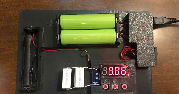
The circuit uses an Arduino Nano microcontroller along with an OLED display, op-amp, MOSFET, resistors, and capacitors. It works by discharging the battery at a constant current set using pulse width modulation. The battery voltage is measured with an analog input. A thermistor also measures battery temperature.
Users can select the discharge current level with two push buttons. As the battery discharges, the Arduino measures the time using a timer. It then calculates capacity in mAh by multiplying current, time, and a conversion factor. The results, along with temperature data, are displayed on the OLED screen.
By testing batteries at different current levels over their full discharge cycle, this circuit helps evaluate a battery's true capacity and state of health. False or degraded batteries can be identified. It also allows monitoring of battery performance over multiple charge/discharge cycles.
The constant current circuit regulates the discharge current for accurate results. Additional features like temperature monitoring provide useful battery data. With its simple design and open-source code, this project makes battery testing affordable and accessible, helping extend battery life and optimize battery-powered devices and systems.
DIY Project #8 - Solar Panel Monitoring Station
For those interested in sustainable energy solutions, an ACS712-based solar panel monitoring project provides insight into the performance of a photovoltaic array over time. The current sensor connects in series with the solar panel output, measuring power produced under different light conditions. A light-dependent resistor or photoresistor additionally detects ambient light levels. An anemometer measures wind speed to correlate with panel cooling effects.
All sensor data logs to an SD card using an Arduino or ESP microcontroller. Connected to the local WiFi network, a custom web app displays live readings and historical performance charts. Users can optimize panel placement and angle based on monitoring angles that produce peak output patterns. Over many months of logging, degradation rates may also be analyzed to plan for necessary panel replacements.
The comprehensive data analysis helps advance a personal understanding of solar energy dynamics and efficiency in unique microclimates. It also serves as an educational tool when shared publicly to demonstrate tangible results of clean power generation from an accessible DIY monitoring setup using current sensing technology.
Expanding the Solar Monitoring Capabilities
The solar monitoring station project provides a foundation for further expanding capabilities through additional sensors, networking, and analysis features:
The monitoring station enclosure is weatherproofed for outdoor installation near the solar panels. A large LCD or ePaper display mounted on the enclosure provides real-time readings of current power production, voltage, ambient light levels, and other environmental factors.
Data logs from the SD card can be downloaded periodically to analyze long-term trends. Charts show daily and seasonal variation in solar output correlated to sunlight hours at different times of year. Tilting the panels towards the equator for winter months compared to summer is one optimization revealed.
Additional sensors may include a Pyranometer to measure solar irradiance in W/m2 directly. Integrating this light intensity data with current power generation provides a performance ratio metric over time. Infrared thermometers aimed at the panels also indicate efficiency losses from excessive heat.
An integrated GSM/GPRS or LoRaWAN transmitter broadcasts readings to an online monitoring dashboard for remote visibility. User accounts log each installation location. Multi-site businesses use it to compare output and maintenance needs between different roof mount locations.
Open-sourcing the code and electrical designs enables a crowdsourced study pooling data from many varied climate regions. Overlays on Google Maps visualize solar potential across communities. Aggregated anonymized statistics spark discussion on how monitoring furthers renewable adoption and grid modernization.
Open hardware licensing encourages a thriving third-party accessory industry. Expandable backplanes add sensors for wind turbines, hydroelectric dams, or other renewable devices to create versatile energy monitoring stations. Low-cost versions using ESP-based microcontrollers bring hands-on STEM learning to classrooms worldwide.
The possibilities continue as current sensing scales sustainable energy projects from simple home installations to big data systems supporting whole communities. It marks an exciting area of innovative application for the humble ACS712 sensor.
DIY Project #9 - Arduino Solar Battery Charger
Harnessing power from the sun not only reduces energy costs but also reliance on polluting fossil fuels. A simple Arduino-based solar battery charger utilizing an ACS712 monitors charging parameters and protects batteries from overcharging.
The sensor measures the current flowing from the solar panel through a diode into a 12V lead-acid battery. Software regulates a MOSFET "pass" transistor that switches the panel on and off to maintain a constant charging voltage. Additional sensing of battery voltage ensures trickle charging at the float stage.
An LCD screen displays voltage, current, and state of charge. Integrated with a weatherproof project box with MC4 solar connectors, it makes an affordable standalone renewable energy solution great for RVs, boats, or remote installations. Open source code also acts as an educational platform.
DIY Project #10 - Motor Controller Speed & Torque Monitoring
Brushless DC motors are increasingly powering robots, CNC machines, and beyond. An ACS712 allows visualizing applied torque and rotational speed for tuning motor controls.
The sensor connects in series with the motor wires, measuring the current draw which correlates to the applied load. An encoder or hall effect sensor outputs RPM to the microcontroller. Custom GUI code graphs both parameters, qualifying motor/controller performance at various duty cycles, PID settings, or mechanical loads in real-time.
Permanent magnet motors find applications wherever automated motion is required. Seeing dynamic operation through current/speed profiling early in the design cycle avoids wasted testing. Engineers developing new motor control strategies also gain valuable analytical insight through measurement.
DIY Project #11 - 3D Printed Powered Wheelchair Control Console
Accessibility opens doors for all. A modular 3D printed electric wheelchair controller powered by a Raspberry Pi brings customizable controls within reach of users.
Two ACS712 current sensors monitor draw on each motor independently. An H-Bridge design provides a bidirectional drive via MOSFET switches. Joysticks, switches, sensors, and screens integrate into a single printed panel for ergonomic accessibility.
Users customize input methods to abilities via open-source code. Onboard monitoring prevents overheating/stalls. Teleoperation expands control to caretakers. Overall it exemplifies how current sensing and digital fabrication synergize to impact lives through inclusive design and independent living positively.
DIY Project #12 - Arduino Smart Sprinkler System
Replacing fixed schedules, a microcontroller-based smart sprinkler automates watering plants only when soil moisture drops using current sensing.
ACS712 modules on each sprinkler zone measure solenoid valve operating current, inferring flow versus no flow states. Additional soil moisture sensors provide zone-level feedback to the controller, and Weather data factors in evapotranspiration needs versus rainfall.
Over time, a watering schedule self-tunes to local hydrologic conditions and plant types via machine learning algorithms. Current flow signatures identify clogged or leaking zones for maintenance. Homeowners save water and dollars with less waste versus conventional timed systems
Comment